Object Dictionary#
Object dictionary holds CAN objects that can be accessed using SDOs and in some cases by PDOs. There are three main groups in which the address space is divided into:
Communication Area
Manufacturer Specific Area
Profile Specific Area
1. Communication Area#
The communication area describes the CANopen objects compliant with CiA301 standard.
0x1000 - Device type#
| Index | Sub Index | Name | Data Type | SDO | PDO | NVM | Range | Default | Units |
| 0x1000 | 0x00 | Device type | UINT32 | RO | - | - | - | 0x00020192 | - |
0x1001 - Error Register#
Indicates whether an error has occured. Currently, only the 0th bit is implemented, that indicates a general error. For a more verbose error and warning status, please see 0x2004 System Status.
| Index | Sub Index | Name | Data Type | SDO | PDO | NVM | Range | Default | Units |
| 0x1001 | 0x00 | Error Register | UINT8 | RO | TX | - | - | 0x00 | - |
| Bit | Meaning |
| 0 | General Error |
0x1008 - Manufacturer Device Name#
| Index | Sub Index | Name | Data Type | SDO | PDO | NVM | Range | Default | Units |
| 0x1008 | 0x00 | Manufacturer Device Name | STR | RO | - | - | - | "MD80" | - |
0x1010 - Store Parameters#
Use this object for saving parameters in non-volatile memory. Works only in “switch on disabled” state. To avoid saving parameters by mistake a value of 0x65766173 has to be explicitly written to 0x1010:1.
| Index | Sub Index | Name | Data Type | SDO | PDO | NVM | Range | Default | Units |
| 0x1010 | 0x01 | Store Parameters | UINT32 | RW | - | - | - | - | - |
0x1017 - Producer Heartbeat Time#
Defines the period of heartbeat message sent by the MD80.
| Index | Sub Index | Name | Data Type | SDO | PDO | NVM | Range | Default | Units |
| 0x1017 | 0x00 | Producer Heartbeat Time | UINT16 | RW | - | - | - | - | - |
0x1600 - Receive PDO1 mapping#
| Index | PDO Index | Name |
| 0x1600 | - | Receive PDO1 mapping |
| 0x1600:1 | 0x6040 | ControlWord |
0x1601 - Receive PDO2 mapping#
| Index | PDO Index | Name |
| 0x1601 | - | Receive PDO2 mapping |
| 0x1601:1 | 0x6040 | ControlWord |
| 0x1601:2 | 0x6060 | Modes Of Operation |
0x1602 - Receive PDO3 mapping#
| Index | PDO Index | Name |
| 0x1602 | - | Receive PDO3 mapping |
| 0x1602:1 | 0x6040 | ControlWord |
| 0x1602:2 | 0x607A | Target Position |
0x1603 - Receive PDO4 mapping#
| Index | PDO Index | Name |
| 0x1603 | - | Receive PDO4 mapping |
| 0x1603:1 | 0x6040 | ControlWord |
| 0x1603:2 | 0x60FF | Target Velocity |
0x1A00 - Transmit PDO1 mapping#
| Index | PDO Index | Name |
| 0x1A00 | - | Transmit PDO1 mapping |
| 0x1A00:1 | 0x6041 | StatusWord |
| 0x1A00:2 | 0x6061 | Modes Of Operation Display |
0x1A01 - Transmit PDO2 mapping#
| Index | PDO Index | Name |
| 0x1A01 | - | Transmit PDO2 mapping |
| 0x1A01:1 | 0x6041 | StatusWord |
| 0x1A01:2 | 0x6064 | Position Actual Value |
0x1A02 - Transmit PDO3 mapping#
| Index | PDO Index | Name |
| 0x1A02 | - | Transmit PDO3 mapping |
| 0x1A02:1 | 0x6041 | StatusWord |
| 0x1A02:2 | 0x606C | Velocity Actual Value |
0x1A03 - Transmit PDO4 mapping#
| Index | PDO Index | Name |
| 0x1A03 | - | Transmit PDO4 mapping |
| 0x1A03:1 | 0x6041 | StatusWord |
| 0x1A03:2 | 0x6077 | Torque Actual Value |
2. Manufacturer Specific Area#
The manufacturer specific area describes the custom CANopen objects, valid only for MD80s.
0x2000 - Motor Settings#
Configures the most important motor settings. This object is especially useful when you want to configure or reconfigure an MD80 for a particular motor. Be sure to save after modification using 0x1010 Store Parameters.
| Index | Sub Index | Name | Data Type | SDO | PDO | NVM | Range | Default | Units |
| 0x2000 | 0x01 | Pole Pairs | UINT32 | RW | - | yes | [2;255] | 0 | - |
| 0x2000 | 0x02 | Torque constant | FLOAT32 | RW | - | yes | - | 0 | Nm/A |
| 0x2000 | 0x03 | Phase Inductance | FLOAT32 | RW | - | yes | [5nH-100mH] | 0 | H |
| 0x2000 | 0x04 | Phase Resistance | FLOAT32 | RW | - | yes | [5mOhm-20Ohm] | 0 | Ohm |
| 0x2000 | 0x05 | Torque Bandwidth | UINT16 | RW | - | yes | 50-2500 | 0 | Hz |
| 0x2000 | 0x06 | Motor Name | STR(20) | RW | - | yes | - | 0 | - |
| 0x2000 | 0x07 | Motor Shutdown Temperature | UINT8 | RW | - | yes | 10-80 | 0 | *C |
| 0x2000 | 0x08 | Gear Ratio | FLOAT32 | RW | - | yes | - | 1 | - |
| 0x2000 | 0x09 | Calibration Mode | UINT8 | RW | - | yes | FULL = 0, NOPPDET = 1 | 0 | - |
| 0x2000 | 0x0A | Can ID | UINT32 | RW | - | yes | 1 - 31 | 1 | - |
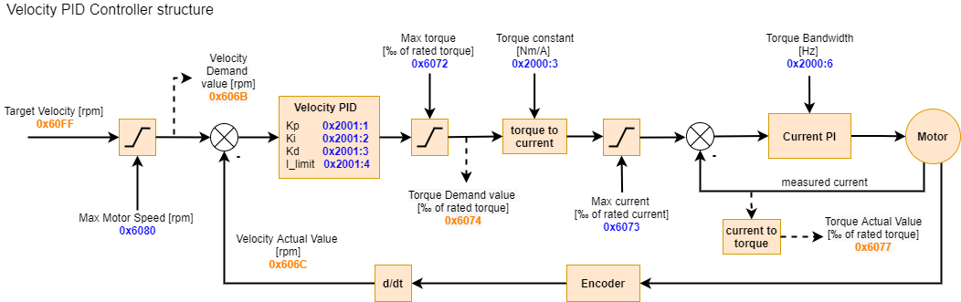
0x2001 - Velocity PID Controller#
Configures the Velocity PID controller gains. Be sure to save after modification using 0x1010 Store Parameters.
| Index | Sub Index | Name | Data Type | SDO | PDO | NVM | Range | Default | Units |
| 0x2001 | 0x01 | Kp | FLOAT32 | RW | - | yes | - | 0 | - |
| 0x2001 | 0x02 | Ki | FLOAT32 | RW | - | yes | - | 0 | - |
| 0x2001 | 0x03 | Kd | FLOAT32 | RW | - | yes | - | 0 | - |
| 0x2001 | 0x04 | Integral Limit | FLOAT32 | RW | - | yes | - | 0 | Nm |
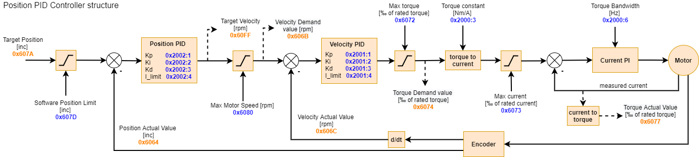
0x2002 - Position PID Controller#
Configures the Position PID controller gains. Be sure to save after modification using 0x1010 Store Parameters.
| Index | Sub Index | Name | Data Type | SDO | PDO | NVM | Range | Default | Units |
| 0x2002 | 0x01 | Kp | FLOAT32 | RW | - | yes | - | 0 | - |
| 0x2002 | 0x02 | Ki | FLOAT32 | RW | - | yes | - | 0 | - |
| 0x2002 | 0x03 | Kd | FLOAT32 | RW | - | yes | - | 0 | - |
| 0x2002 | 0x04 | Integral Limit | FLOAT32 | RW | - | yes | - | 0 | rad/s |
0x2003 - System Command#
Allows to issue a system command. Write a non-zero value to start a specific action. Actions work only in “switch on disabled” state and “service” (-2) operation mode.
| Index | Sub Index | Name | Data Type | SDO | PDO | NVM | Range | Default | Units |
| 0x2003 | 0x01 | Blink LEDs | BOOL | RW | - | - | - | 0 | - |
| 0x2003 | 0x02 | Reset Controller | BOOL | RW | - | - | - | 0 | - |
| 0x2003 | 0x03 | Run Calibration | BOOL | RW | - | - | - | 0 | - |
| 0x2003 | 0x04 | Run Output Encoder Calibration | BOOL | RW | - | - | - | 0 | - |
| 0x2003 | 0x05 | Set Zero | BOOL | RW | - | - | - | 0 | - |
| 0x2003 | 0x06 | Calibrate Current PI Gains | BOOL | RW | - | - | - | 0 | - |
0x2004 - System Status#
Allows to read System status. Each specific status is a UINT32, where lower bits (0-15) indicate errors, and higher bits (16-31) indicate warnings. Please see the Status section to see how to decode the status to individual fields.
| Index | Sub Index | Name | Data Type | SDO | PDO | NVM | Range | Default | Units |
| 0x2004 | 0x01 | Main Encoder Status | UINT32 | RW | - | - | - | 0 | - |
| 0x2003 | 0x02 | Output Encoder Status | UINT32 | RW | - | - | - | 0 | - |
| 0x2003 | 0x03 | Calibration Status | UINT32 | RW | - | - | - | 0 | - |
| 0x2003 | 0x04 | Bridge Status | UINT32 | RW | - | - | - | 0 | - |
| 0x2003 | 0x05 | Hardware Status | UINT32 | RW | - | - | - | 0 | - |
| 0x2003 | 0x02 | Homing Status | UINT32 | RW | - | - | - | 0 | - |
| 0x2003 | 0x02 | Motion Status | UINT32 | RW | - | - | - | 0 | - |
0x2005 - Output Encoder#
Output encoder related record.
| Index | Sub Index | Name | Data Type | SDO | PDO | NVM | Range | Default | Units |
| 0x2005 | 0x01 | Type | UINT32 | RW | - | yes | 1 (AS5047_CENTER), 2 (AS5047_OFFAXIS), 3 (MB053SFA17BENT00) | 0 | - |
| 0x2003 | 0x02 | Calibration Mode | UINT32 | RW | - | yes | FULL = 0, DIRONLY = 1 | 0 | - |
| 0x2003 | 0x03 | Mode | UINT32 | RW | - | yes | NONE = 0, STARTUP = 1, MOTION = 2, REPORT = 3 | 0 | - |
| 0x2003 | 0x04 | Position | FLOAT32 | RO | TX | - | - | 0.0 | rad |
| 0x2003 | 0x05 | Velocity | FLOAT32 | RO | TX | - | - | 0.0 | rad/s |
0x2006 - Temperature#
Motor and mosfet temperature readout record.
| Index | Sub Index | Name | Data Type | SDO | PDO | NVM | Range | Default | Units |
| 0x2006 | 0x01 | Motor Temperature | FLOAT32 | RO | TX | - | - | 0.0 | - |
| 0x2006 | 0x02 | Mosfet Temperature | FLOAT32 | RO | TX | - | - | 0.0 | - |
3. Profile Specific Area#
The profile specific area describes the CANopen objects compliant with CiA402 standard.
0x6040 - Control Word#
Control word is used to change the state of the internal CiA402 state machine implemented on the drive.
| Index | Sub Index | Name | Data Type | SDO | PDO | NVM | Range | Default | Units |
| 0x6040 | 0x00 | Control Word | UINT16 | RW | RX | - | - | 0x00 | - |
The state machine is defined as follows:
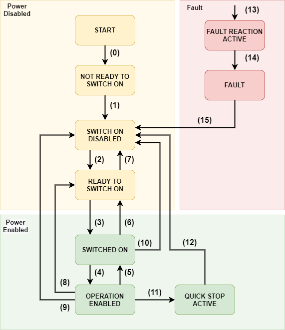
All the transitions are based on the control word. The current state can be read using the status word (0x6041).
| Command | Reset Fault (bit 7) | Enable Operation (bit 3) | Quick Stop (bit 2) | Disable Voltage (bit 1) | Switch On (bit 0) | Decimal value |
| Shutdown | 0 | X | 1 | 1 | 0 | 6 |
| Switch on | 0 | 0 | 1 | 1 | 1 | 7 |
| Switch on and Enable Operation | 0 | 1 | 1 | 1 | 1 | 15 |
| Disable Voltage | 0 | X | X | 0 | X | 0 |
| Quick Stop | 0 | X | 0 | 1 | X | 2 |
| Disable operation | 0 | 0 | 1 | 1 | 1 | 7 |
| Enable operation | 0 | 1 | 1 | 1 | 1 | 15 |
| Fault reset | 0->1 | X | X | X | X | 128 |
X means “do not care”
Example:
To put the drive into operational mode set:
Control word = 6 (dec) (Shutdown cmd)
Control word = 15 (dec) (Switch on and Enable Operation cmds)
The events and respective transitions are gathered in the table below:
| Transition | Event | Internal action |
| 0 | Automatic transition after power up | Drive internal initialization |
| 1 | Automatic transition after drives internal initialization | Object dictionary is initalized with NVM data |
| 2 | Shutdown command received | None |
| 3 | Switch on command received | None |
| 4 | Enable operation command received | Current controllers are on, power is applied to the motor |
| 5 | Disable operation command received | Current controllers are off, power is not applied to the motor |
| 6 | Shutdown command received | Current controllers are turned off |
| 7 | Quick stop command received | Current controllers are turned off |
| 8 | Shutdown command received | Current controllers are turned off |
| 9 | Disable voltage command received | Current controllers are turned off |
| 10 | Disable voltage / Quick stop command received | Current controllers are turned off |
| 11 | Quick stop command received | Quick stop action is enabled. The drive decelerates and transits to SWITCH ON DISABLED |
| 12 | Automatic transition when quick stop is completed | Current controllers are turned off |
| 13 | Fault ocurred | Current controllers are turned off |
| 14 | Automatic transition to fault state | None |
| 15 | Fault reset command received | Fault is cleared if not critical |
0x6041 - Status Word#
| Index | Sub Index | Name | Data Type | SDO | PDO | NVM | Range | Default | Units |
| 0x6041 | 0x00 | Status Word | UINT16 | RO | TX | - | - | 0x00 | - |
| Status Word | State Machine State |
| xxxx xxxx x0xx 0000 | Not ready to switch on |
| xxxx xxxx x1xx 0000 | Switch on disabled |
| xxxx xxxx x01x 0001 | Ready to switch on |
| xxxx xxxx x01x 0011 | Switched on |
| xxxx xxxx x01x 0111 | Operation Enabled |
| xxxx xxxx x00x 0111 | Quick stop active |
| xxxx xxxx x0xx 1111 | Fault reaction active |
| xxxx xxxx x0xx 1000 | Quick stop active |
bit 10 of the statusword indicates the current target has been reached (1) or not (0). This bit is motion mode - dependent, meaning for example in position mode it indicates the position has been reached (within a 0x6067 Position Window margin), and in velocity mode that a velocity target has been reached (within 0x606D Velocity Window).
bit 11 of the statusword indicates whether any of the internal limits was active during current power up - for more information on which limit is active, check the 0x2004:7 Motion Status.
0x6060 - Modes Of Operation#
Use this object to request a motion mode change. The actual mode is reflected in 0x6061 Modes Of Operation Display.
| Index | Sub Index | Name | Data Type | SDO | PDO | NVM | Range | Default | Units |
| 0x6060 | 0x00 | Modes Of Operation | INT8 | RW | RX | - | - | 0x00 | - |
| Value | Mode |
| -2 | Service |
| 0 | Idle |
| 1 | Profile Position |
| 3 | Profile Velocity |
| 8 | Cyclic Sync Position |
| 9 | Cyclic Sync Velocity |
Service#
Mode in which System Commands can be issued.
Idle#
Default state of the drive. No torque is produced, motor phases are shorted to GND which causes a damping sensation on the shaft.
Profile position#
Profile position mode uses a trapeziodal trajectory generator on top of the Position PID controller. Allows to perform smooth point-to-point movements.
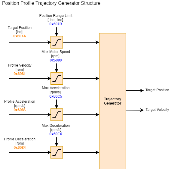
Profile velocity#
Profile velocity mode uses a trapeziodal trajectory generator on top of the Velocity PID controller. Allows to reach a certain velocity with a constant acceleration / deceleration.
Cyclic Sync Position#
Raw position PID controller. Target position is reached as fast as possible, respecting the position range limits, max velocity, and max torque limit. To achieve smooth trajectories new setpoints need to be sent with high frequency.
Cyclic Sync Velocity#
Raw velocity PID controller. Target velocity is reached as fast as possible, respecting the max velocity limit, and max torque limit. To achieve smooth acceleration new velocity setpoints need to be sent with high frequency.
0x6061 - Modes Of Operation Display#
Use this object to read current motion mode
| Index | Sub Index | Name | Data Type | SDO | PDO | NVM | Range | Default | Units |
| 0x6061 | 0x00 | Modes Of Operation Display | INT8 | RO | TX | - | - | 0x00 | - |
| Value | Mode |
| -2 | Service |
| 0 | Idle |
| 1 | Profile Position |
| 3 | Profile Velocity |
| 8 | Cyclic Sync Position |
| 9 | Cyclic Sync Velocity |
0x6062 - Position Demand Value#
This object provides the target position for Position PID controller, after the limits have been applied. Expressed in encoder increments.
| Index | Sub Index | Name | Data Type | SDO | PDO | NVM | Range | Default | Units |
| 0x6062 | 0x00 | Position Demand Value | INT32 | RO | - | - | - | 0x00 | INC |
0x6064 - Position Actual Value#
Provides the actual position value read from the encoder, expressed in the output shaft reference frame. Expressed in encoder increments.
| Index | Sub Index | Name | Data Type | SDO | PDO | NVM | Range | Default | Units |
| 0x6064 | 0x00 | Position Actual Value | INT32 | RO | TX | - | - | 0x00 | INC |
0x6067 - Position Window#
Sets the size of the position window within which the target position is considered to have been reached. This value is symmetrically added to both sides of the target position value. Expressed in encoder increments.
| Index | Sub Index | Name | Data Type | SDO | PDO | NVM | Range | Default | Units |
| 0x6067 | 0x00 | Position Window | INT32 | RW | TX | - | - | 0x00 | INC |
0x606B - Velocity Demand Value#
Provides the target velocity value for the Velocity PID controller, after the limits have been applied. Expressed in RPM.
| Index | Sub Index | Name | Data Type | SDO | PDO | NVM | Range | Default | Units |
| 0x606B | 0x00 | Velocity Demand Value | INT32 | RO | TX | - | - | 0x00 | RPM |
0x606C - Velocity Actual Value#
Provides the actual velocity value read from the encoder, expressed in the output shaft reference frame. Expressed in RPM.
| Index | Sub Index | Name | Data Type | SDO | PDO | NVM | Range | Default | Units |
| 0x606C | 0x00 | Velocity Actual Value | INT32 | RO | TX | - | - | 0x00 | RPM |
0x606D - Velocity Window#
Sets the size of the velocity window within which the target velocity is considered to have been reached. This value is symmetrically added to both sides of the target velocity value. Expressed in RPM.
| Index | Sub Index | Name | Data Type | SDO | PDO | NVM | Range | Default | Units |
| 0x606D | 0x00 | Velocity Window | INT32 | RW | TX | - | - | 0x00 | RPM |
0x6072 - Max Torque#
Configures the maximum allowed torque in the motor. The value is expressed in permille of rated torque. Example: rated torque of the motor is 1Nm, and the maximum is 2Nm. The Max Torque object should equal to 2000.
| Index | Sub Index | Name | Data Type | SDO | PDO | NVM | Range | Default | Units |
| 0x6072 | 0x00 | Max Torque | UNT16 | RW | RX | yes | 32767 | 0x00 | - |
0x6073 - Max Current#
Configures the maximum allowed phase current in the motor. The value is expressed in permille of rated current. Example: rated current of the motor is 15A, and the maximum is 30A. The Max Current object should equal to 2000.
| Index | Sub Index | Name | Data Type | SDO | PDO | NVM | Range | Default | Units |
| 0x6073 | 0x00 | Max Current | UNT16 | RW | RX | yes | 50000 | 0x00 | - |
0x6075 - Motor Rated Current#
Configures the motor rated current expressed in mA. This object is a reference for parameters such as 0x6073 Max Current. The value should be taken from the motor’s datasheet.
| Index | Sub Index | Name | Data Type | SDO | PDO | NVM | Range | Default | Units |
| 0x6075 | 0x00 | Motor Rated Current | INT32 | RW | - | yes | 1000000 | 0x00 | mA |
0x6076 - Motor Rated Torque#
Configures the motor rated torque expressed in mNm. This object is a reference for parameters such as 0x6072 Max Torque. The value should be taken from the motor’s datasheet.
| Index | Sub Index | Name | Data Type | SDO | PDO | NVM | Range | Default | Units |
| 0x6076 | 0x00 | Motor Rated Torque | INT32 | RW | - | yes | 1000000 | 0x00 | mNm |
0x6077 - Torque Actual Value#
Provides the actual velocity value read from the encoder, expressed in the output shaft reference frame. Expressed in permille of 0x6076 Motor Rated Torque.
| Index | Sub Index | Name | Data Type | SDO | PDO | NVM | Range | Default | Units |
| 0x6077 | 0x00 | Torque Actual Value | INT16 | RO | TX | - | - | 0x00 | - |
0x6079 - DC Link Circuit Voltage#
Provides the bus voltage measured by the motor controller in mV.
| Index | Sub Index | Name | Data Type | SDO | PDO | NVM | Range | Default | Units |
| 0x6079 | 0x00 | DC Link Circuit Voltage | UNT32 | RO | RX | - | - | 0x00 | mV |
0x607A - Target Position#
Sets the target position for all motion modes.
| Index | Sub Index | Name | Data Type | SDO | PDO | NVM | Range | Default | Units |
| 0x607A | 0x00 | Target Position | INT32 | RW | RX | - | - | 0x00 | inc |
0x607D - Software Position Limit#
Configures software limits that each new target position is checked against, and clipped if needed.
| Index | Sub Index | Name | Data Type | SDO | PDO | NVM | Range | Default | Units |
| 0x607D | 0x01 | Min Position Limit | INT32 | RW | RX | yes | - | 0x00 | inc |
| Index | Sub Index | Name | Data Type | SDO | PDO | NVM | Range | Default | Units |
| 0x607D | 0x02 | Max Position Limit | INT32 | RW | RX | yes | - | 0x00 | inc |
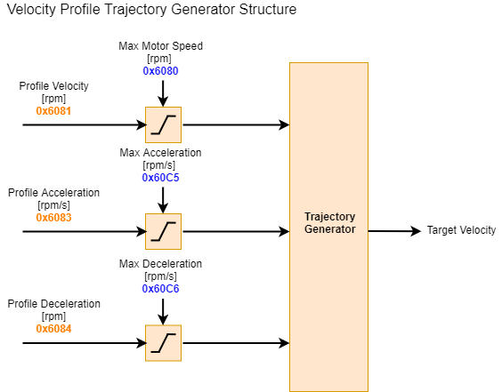
0x6080 - Max Motor Speed#
Sets the maximum allowed velocity of the actuator’s output shaft in both directions.
| Index | Sub Index | Name | Data Type | SDO | PDO | NVM | Range | Default | Units |
| 0x6080 | 0x00 | Max Motor Speed | UINT32 | RW | RX | - | - | 1000 | RPM |
0x6081 - Profile Velocity#
Configures the target velocity for the profile position mode. If this value is greater than 0x6080 Max Motor Speed, it will be limited to Max Motor Speed.
| Index | Sub Index | Name | Data Type | SDO | PDO | NVM | Range | Default | Units |
| 0x6081 | 0x00 | Profile Velocity | UINT32 | RW | RX | yes | - | 0 | RPM |
0x6083 - Profile Acceleration#
Configures the acceleration for profile position and profile velocity modes.
| Index | Sub Index | Name | Data Type | SDO | PDO | NVM | Range | Default | Units |
| 0x6083 | 0x00 | Profile Acceleration | UINT32 | RW | RX | - | - | 0 | RPM/s |
0x6084 - Profile Deceleration#
Configures the deceleration for profile position and profile velocity modes.
| Index | Sub Index | Name | Data Type | SDO | PDO | NVM | Range | Default | Units |
| 0x6084 | 0x00 | Profile Deceleration | UINT32 | RW | RX | - | - | 0 | RPM/s |
0x60FF - Target Velocity#
Sets the target velocity for all motion modes.
| Index | Sub Index | Name | Data Type | SDO | PDO | NVM | Range | Default | Units |
| 0x60FF | 0x00 | Target Velocity | INT32 | RW | RX | - | - | 0 | RPM |
0x6502 - Supported Drive Modes#
Indicates the supported drive modes (binary value).
| Index | Sub Index | Name | Data Type | SDO | PDO | NVM | Range | Default | Units |
| 0x6502 | 0x00 | Supported Drive Modes | INT32 | RO | - | - | - | 647 | - |