MD80#
General parameters#
MD80 is a brushless motor controller. It can work with a variety of motors and reducers that can be precisely matched to the users’ specifications. All MD80 variants are using an advanced motor control algorithm (FOC), a high-resolution encoder, a high-speed FDCAN communication bus, and a common communication interface. The controller feratures position PID, velocity PID, impedance, raw torque, profile position and profile velocity operation modes. MD80 can be easily daisy-chained, for easy connection of many drives in a single control network.
Hint
You can easily check your MD80 version using the mdtool setup info command.
General parameters table for MD80 V2.0 and V2.1:
Parameter |
Value |
|---|---|
Input Voltage |
10 - 48 VDC |
Nominal Input Voltage |
24 VDC |
Max Input Current |
10 A |
Max Continuous Phase Current |
20 A |
Max Peak Phase Current (t = 2 s) |
80 A |
Built-in software-controlled termination resistor |
optional |
FDCAN Baudrate (adjustable) |
1/2/5/8 Mbps |
Position PID Controller Execution Frequency |
1 kHz |
Velocity PID Controller Execution Frequency |
5 kHz |
Impedance Controller Execution Frequency |
40 kHz |
Torque Control Execution Frequency |
40 kHz |
Torque Bandwidth (adjustable) |
50 Hz - 2.5 kHz |
External encoder connector (SPI, RS422) |
yes |
External 5V power supply max current |
150 mA |
General parameters table for MD80 HW1.1, HV1.3 and older:
Parameter |
Value |
|---|---|
Input Voltage |
18 - 28 VDC |
Nominal Input Voltage |
24 VDC |
Max Input Current |
10 A |
Max Continuous Phase Current |
20 A |
Max Peak Phase Current (t = 4 s) |
40 A |
FDCAN Baudrate (adjustable) |
1/2/5/8 Mbps |
Position PID Controller Execution Frequency |
1 kHz |
Velocity PID Controller Execution Frequency |
5 kHz |
Impedance Controller Execution Frequency |
40 kHz |
Torque Control Execution Frequency |
40 kHz |
Torque Bandwidth (adjustable) |
50 Hz - 2.5 kHz |
Connectors pinout#
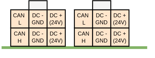
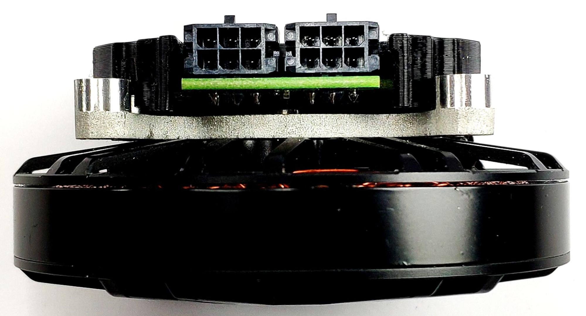
The connectors used in the system on the CAN FD side are MOLEX Micro-Fit series 3.0. Both connectors are connected in parallel for easy daisy-chaining. The connector pinout is presented below:
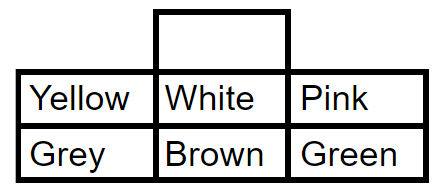
The colors of the corresponding wires in the Molex socket, as supplied by MAB (looking from the side of the wires):
Warning
Always make sure CAN bus lines are not shorted to the positive power rail. Applying supply voltage to these pins will cause permanent damage to the controller!
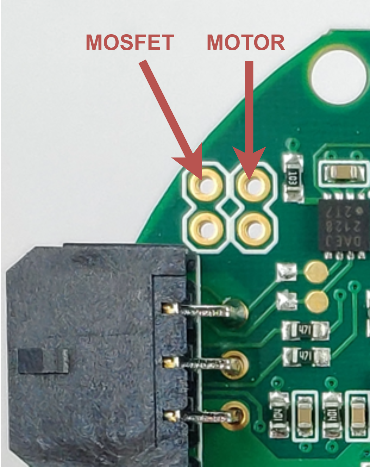
All MD80 versions have the capability to measure the MOSFET and motor temperature. This is to ensure the safe operation of the driver and motor. The motor shutdown temperature is configurable up to 140\(^\circ\)C max with a hysteresis of 20\(^\circ\)C. The driver shutdown temperature is fixed at 100\(^\circ\)C with a hysteresis of 20\(^\circ\)C.
The connectors in the case of the HW1.1 and HV1.3 versions are located as follows:
In the case of the MD80 HW V2.0 the MOSFET thermistor is built-in directly under the power stage and only the motor thermistor connector is available:
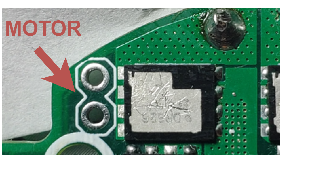
Note
For the current version of the board we recommend using NTCMHP10K thermistors. Using other thermistors may result in imprecise temperature readout.
Note
On older (<2.2) designs NTCMHP100K is recommended.
Since version HW V2.0 the PCB is equipped with an auxiliary connector (picoblade series connector 53048-0650 compatible with 797580006 and 510210600) for communication with output encoders. The connector pinout is available below:
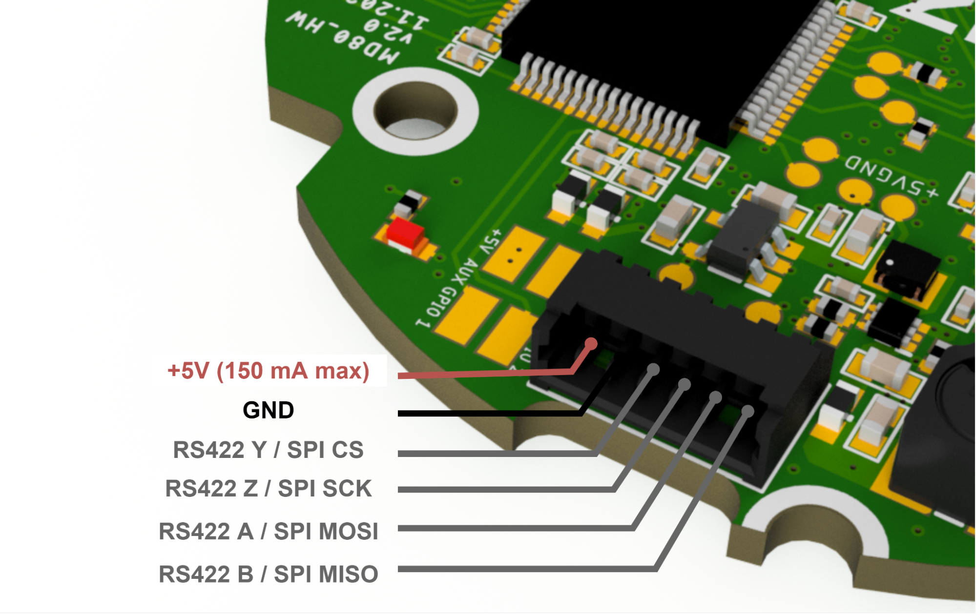
External connector pin functions (RS422 / SPI) are selectable using resistors on the bottom PCB side.
Warning
The auxiliary connector pins are 3.3V tolerant. Applying 5V to these pins will cause permanent damage to the controller!
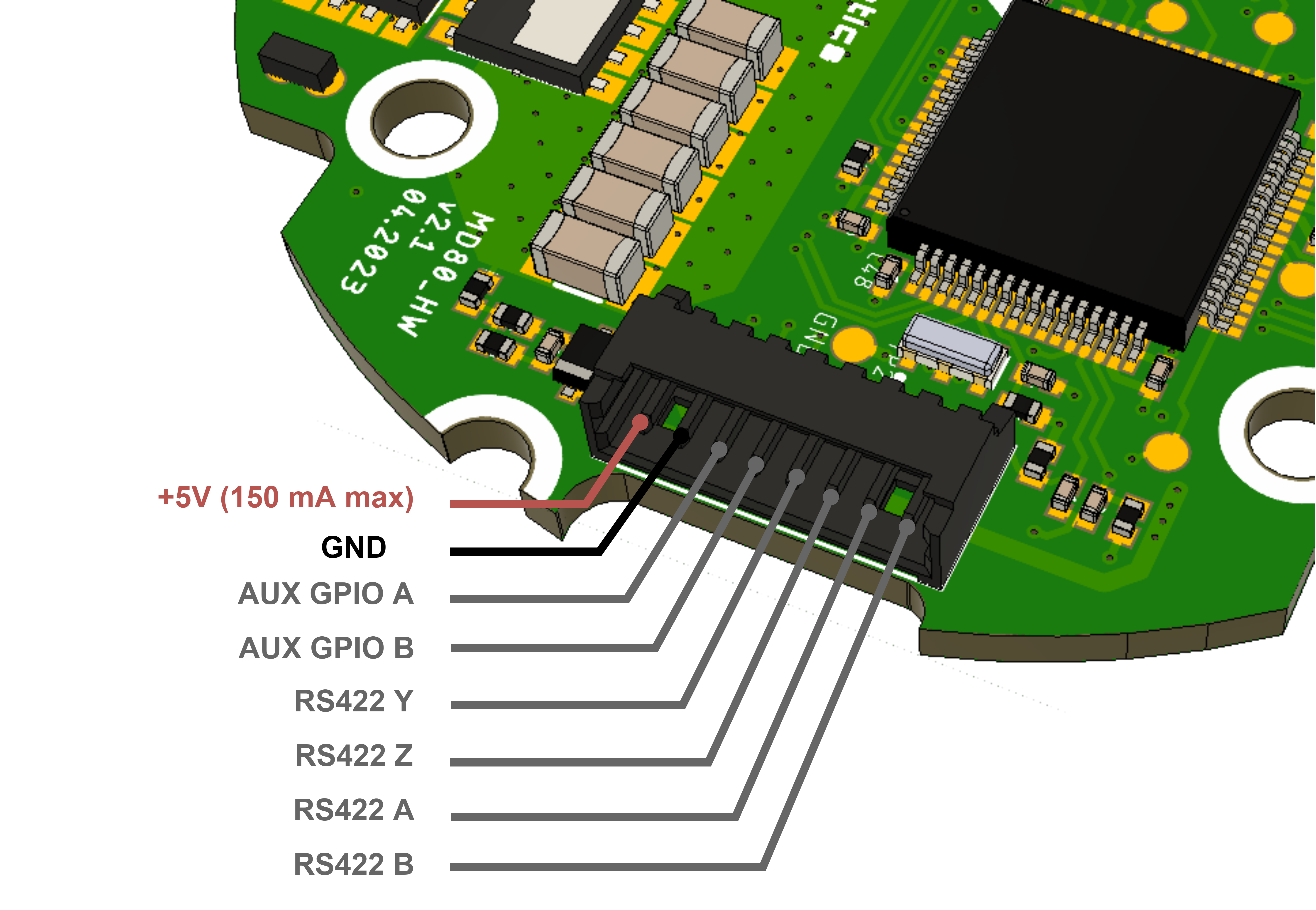
The HW2.1 features a separate RS422 connector. Thus the AUX1 connector features only the SPI singals, while AUX2 is dedicated for the RS422 communication bus:

We are able to integrate custom functions such as GPIOs for external sensors and indicators. For more information please contact us: contact@mabrobotics.pl