Principle of operation#
CANdle can work in two different modes: CONFIG and UPDATE. When in CONFIG mode, it works as a traditional translator device between two selected buses - USB/SPI/UART and FDCAN. This mode is used to set up the drives and prepare them for a low-latency operation in the UPDATE mode. When the configuration is done the user calls candle.begin() which starts a low-latency continuous connection with the MD controllers. In the UPDATE mode, you are not allowed to call the config functions. To make them easier to recognize, each config function starts with a config keyword. The user exits the UPDATE mode using candle.end() method.
When in Update mode the communication speed is dictated by the number of drives attached to the bus. Please see the latency section for maximum communication speeds.
Generally, a program using CANdle should follow the workflow below:
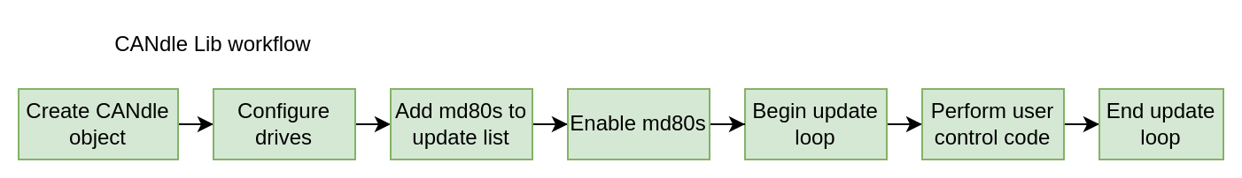
Creating a Candle object creates a class that will hold all the data and provides an API for the user. During the creation of the class, the software will attach itself to the ttyACMx port used by the CANdle, or SPI/UART bus if CANdle HAT is considered. It will also perform a reset operation on the device and set up basic parameters. This ensures that the device is in the known state at the start of the program. When an object is created, the CANdle is in the CONFIG state.
Now the configuration of the drives can be done. As a rule of thumb, all class methods starting with the word ‘config’ can be used here. They do not require adding MDxx to the update list, just require an ID of the drive to talk to. This is a good place to set current limits, change FDCAN parameters, or save data to flash.
Note
This is also a good place to call Candle::ping(), this will trigger the CANdle device to send an FDCAN frame to all valid FDCAN IDs. The method will return a vector of all IDs that have responded. This can be used to check if all the drives have power and if all communication is set up correctly.
The next step is adding MDs to the update list. To do so, use Candle::addMd80() method, with an FDCAN ID (drive ID) as an argument. This will trigger CANdle to quickly check if the drive is available on the bus at the ID, and if it is, the CANdle device will add the drive to its internal list and send an acknowledgment to the CANdle lib. If the drive is successfully added the addMd80() method will add this particular MDxx to its internal vector for future use and return true.
When all drives have been added, the drives should be ready to move. This can be done with methods starting with the “control(…)” keyword. Firstly the control mode should be set, then the zero position set (if desired), and finally the drives can be enabled by using Candle::controlMd80Enable() method.
Note
Sending an ENABLE frame will start the CAN Watchdog Timer. If no commands follow, the drive will shut itself down.
When all drives are enabled, Candle::begin() can be called. This will set the CANdle (both device and library) to UPDATE state. The device will immediately start sending command frames to the MDs. From now on the library will no longer accept config* methods. Right now it is up to the user to decide what to do. After the first 10 milliseconds, the whole MDxx vector will be updated with the most recent data from MDs and the control code can be executed to start moving the drives.
Individual drives can be accessed via Candle::md80s vector. The vector holds instances of ‘Md80’ class, with methods giving access to every MD series motor controller control mode. Latest data from md80’s responses can be accessed with Md80::getPosition(), Md80::getVelocity(), Md80::getTorque(), Md80::getErrorVector().
Note
As the communication is done in the background, it is up to the user to take care of the software timing here. If you for example set a position command, but don’t put any delay after it, the program will get to an end, disabling the communication and the servo drives, without you seeing any movement!
When the control code finishes, the Candle::end() method should be called. This will ensure a ‘clean exit’ meaning a properly closed communication on both USB and FDCAN side. Candle::begin() can be called later to resume communication if needed.
USB bus#
The USB bus is the most common one, used in both CANdle and CANdle HAT. This is one of the slowest communication bus when it comes to performance, due to the non-realtime nature of the host, however, it’s the easiest one to set up and test. Since the USB communication interface is not well-suited for real-time applications due to random host delays the update rates are dependent on your master controller device.
Hint
We highly recommend using the USB bus set up for the first run.
SPI bus#
The SPI bus is only available on CANdle HAT devices. It’s the fastest possible bus that can be used to communicate with the MD series motor controller controllers using CANdle HAT. Together with the RT-PATCH’ed kernel of the system, you will get the best performance.
Hint
CANdle HAT in SPI mode works with all FDCAN speeds, however, we advise setting it to 8M for the best performance.
Note
Since it needs some additional configuration on Single Board Computers such as Raspberry PI, we recommend starting playing with it after getting accustomed to the ecosystem using the USB bus.
UART#
The UART bus is only available on CANdle HAT devices. Its speed on Raspberry PI microcomputers with CANdle HAT is comparable to that of USB, so it should be only used as an emergency bus when the SPI and USB ports are not available.
Note
CANdle HAT in UART mode works with all FDCAN speeds, however, we advise setting it to 8M for the best performance.