Calibration#
Calibration should be performed when the MD80 controller is first mounted to the motor or when anything changes in the motor-controller assembly. It has three main stages during which specific parameters of the setup are measured and saved.
Note
The calibration has to be performed on a motor that is free to rotate with no load attached to its output shaft. If the calibration fails, you will see errors when executing the mdtool setup info command. If the failure is essential to the motor’s operation the MD80 will remain disabled till the next calibration attempt.
Pole pairs detection#
In the first stage the motor will execute one full motor rotor rotation in order to check if the pole pair count is correctly configured. If the detected number of pole pairs is not consistent with the number that was typed in the *.cfg file during motor setup the calibration will fail and an error ERROR_POLE_PAIR_DET will be shown until the next calibration attempt. If you are unsure about the number of pole pairs (you can check it by counting magnets and dividing it by 2) just place zero in the *.cfg file. Then the pole pairs will be automatically detected.
Encoder eccentricity#
Encoder eccentricity is the second measurement that takes place. During this part, the motor performs a slow single rotation in both directions to assess the amount of error due to non-axial encoder placement.
Motor resistance and inductance#
Motor parameters - resistance and inductance are measured in order to calculate the correct current PI controller gains to achieve a certain torque bandwidth (please see the section below). The parameters are measured in the DQ reference frame meaning the resultant resistance and inductance values have to be transformed from either line-to-line quantities or phase quantities.
Torque bandwidth#
Even though the torque command on MD80 controllers seems to be applied instantaneously, in reality, it’s not the case. As in every system, there’s a response to the command which depends on the system itself and the controller gains. A parameter called bandwidth was introduced to describe how fast the output of a system reacts to the changing input. Calibrating the motor for a certain torque bandwidth requires measuring motor parameters. This happens in the last calibration stage and manifests as an audible sound (beep).
The torque bandwidth default setting is set using the motor config file. It can be set to anywhere from 50 Hz to 2.5 kHz, however it is important to note that higher torque bandwidth causes a higher audible noise level. Please see the mdtool setup calibration command for more details on calibrating the actuators.
When the system that you’re designing is a highly dynamic one, you want the torque bandwidth to be higher than the default setting of 50 Hz. Start by calibrating the drives for 1 kHz torque bandwidth, and if you see this is still not enough you can increase it further.
Output Encoder Calibration#
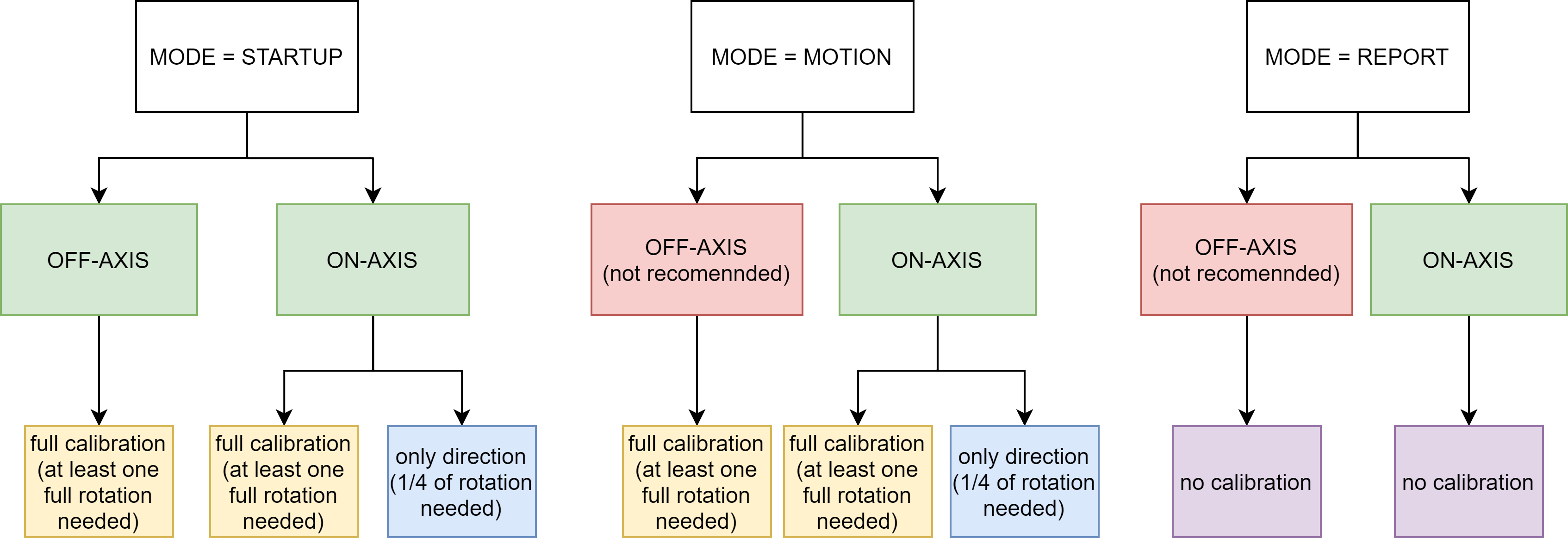
The output encoder calibration routine is used to recognize the correct direction of rotation, and record the correction lookup-table to account for non-axial placement of the encoder in respect to the magnet.
Warning
The full calibration routine rotates the actuators output shaft by more than one single rotation in the FULL calibration mode. Please make sure the shaft is free to rotate during the test.
In case your setup is not able to complete a full rotation due to mechanical constraints you can set the output encoder calibration mode to DIRONLY in your *.cfg file in the [output encoder] section. This way the calibration will end on the first stage - checking the correct direction of rotation, so only 1/4 of a full rotation is needed. Please note that this is not possible using off-axis encoder - it requires a full calibration routine.
To run the routine, use the mdtool setup calibration_out command. After completing the routine the MD80 will reboot and after that it is recommended to run the mdtool setup info command in order to make sure the setup reports no errors:
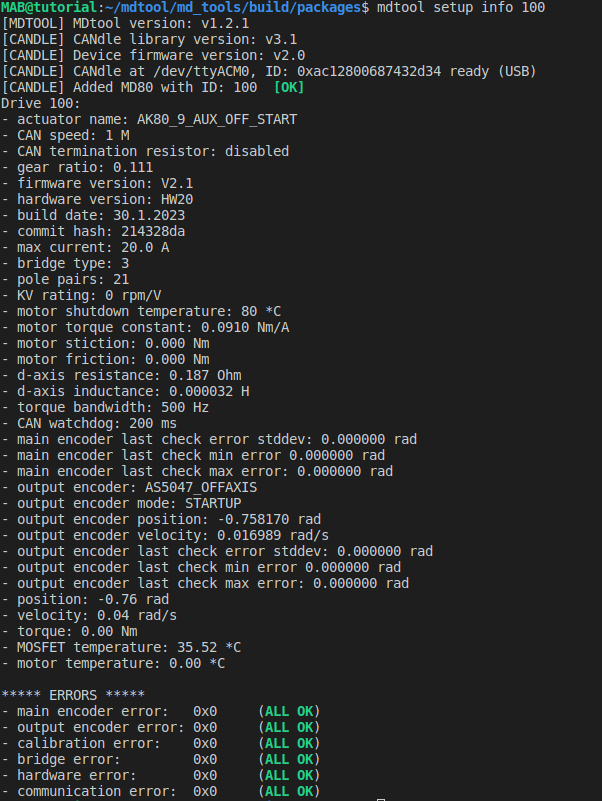
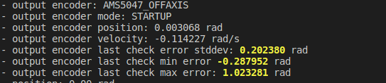
The output encoder parameters are rather straightforward, except the “output encoder last check” errors. These values are filled during the output encoder check routine, which can be run using mdtool test encoder output. These params represent the output encoder errors (max, min and standard deviation) with respect to the main encoder mounted on the PCB. This means that if there are large inaccuracies during the calibration, or the output encoder moves in your setup, you can always check how accurate it is by running the check_aux routine.
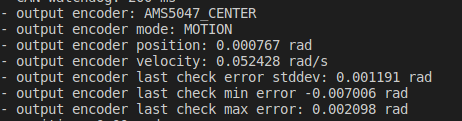
Example errors for AS5047_CENTER:
Example errors for AS5047_OFFAXIS:
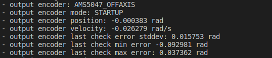
As can be seen, the non-axial encoder features larger errors, and thus can be utilized only for initial position determination rather than output shaft control. In case the errors get too large they will turn yellow after running mdtool test encoder output command indicating there might be a problem with your setup:
Note
These errors will limit the maximum gear ratio that can be used to unambiguously determine the startup output shaft position. Be sure to keep them as low as possible in your setup.