Quick Start Guide#
Before first use#
Here are some things to look out for while playing with the MD x CANdle ecosystem for the first time:
Always stay cautious when dealing with actuators. Even though they don’t seem like it, they may severely hurt you when unintentional movement occurs. It’s recommended to fix the actuator to the workbench.
Get accustomed to the safety limits section of this document. While developing your application be sure to keep the limits low, and only if you are sure you know what you’re doing - increase the limits.
We recommend using power supply sources that can work in two quadrants - meaning they can supply and dissipate some of the energy produced by the motor in case it works as a generator. Old trafo-based power supplies usually block current coming into the power supply, causing overvoltage events on the MD80s. The best choice is to use LiPo batteries or at least SMPS power supplies.
Video tutorials#
Check out our video tutorials if you prefer this way of presentation:
Guide on how to set up a new MD series motor controller to work with a motor of your choice: MD x CANdle - Brushless Motor Setup Guide
Quick startup guide - watch when your motor is already configured and you’d like to try the examples: MD x CANdle - Getting Started Tutorial
MDtool guide - a short introduction to MDtool and its basic commands (at this point the MDtool has evolved, however, the main principles are the same) MD x CANdle - MDtool
Motion modes guide - an introduction to motion modes available on MD series motor controller MD x CANdle - motion modes
ROS/ROS2 startup guide - an introduction to ROS/ROS2 drivers for MD series motor controller MD x CANdle - ROS/ROS2 startup guide
Configuring the MD series controller for a new motor#
MDtool can be used to set up a new motor to work with the MD series motor controller controller. This approach simplifies the configuration process so that the end user can reconfigure the MD series controller driver to work with almost any brushless motor.
Warning
These steps are universal between the controller hardware versions, however, be sure to always check the maximum ratings before applying voltage to the controller.
First, make sure the MD controller can work with your motor. A vast majority of hobby motors will be suitable, although too big motors in terms of power and gimbal motors ( with high phase resistance) might not work as expected. Be sure to contact us before you proceed with a gimbal or high-power motor (over 500W peak power).
Place the diametrically magnetized magnet on the motor shaft and mount the MD controller firmly, centered above the magnet.
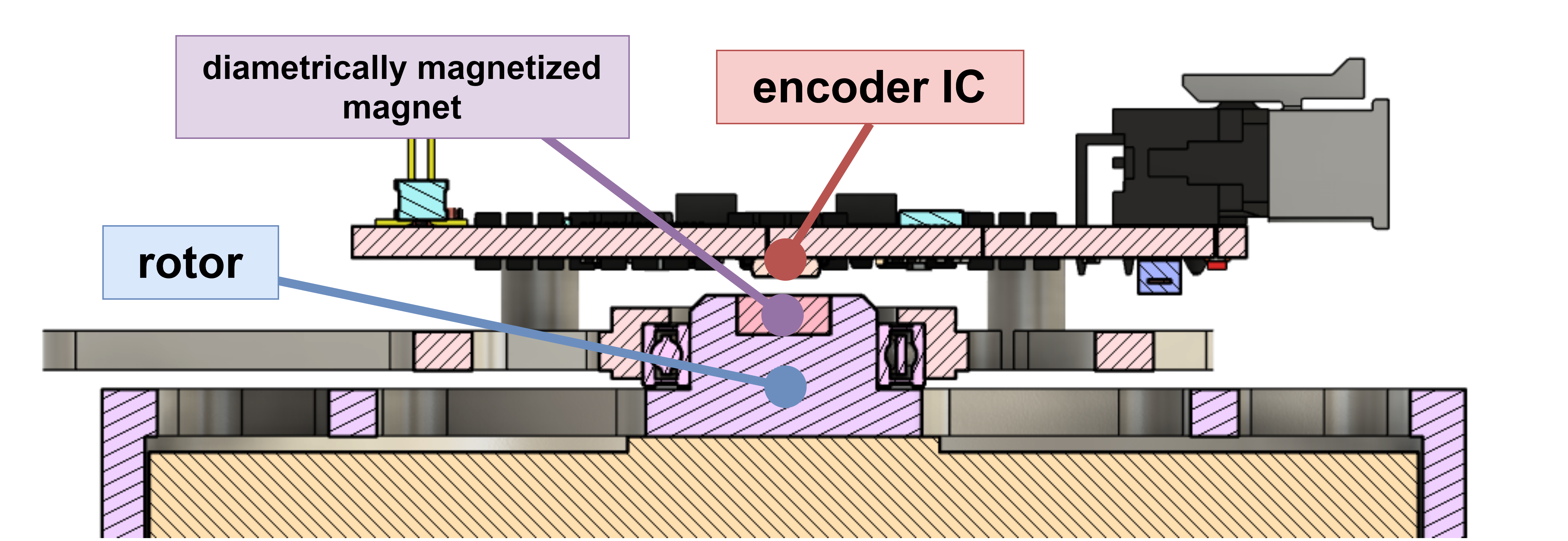
Fig. 1 Magnet - encoder placement cross section#
The optimal height between the magnet and the encoder IC is 1mm. The magnet and the encoder must be on the same rotation axis.
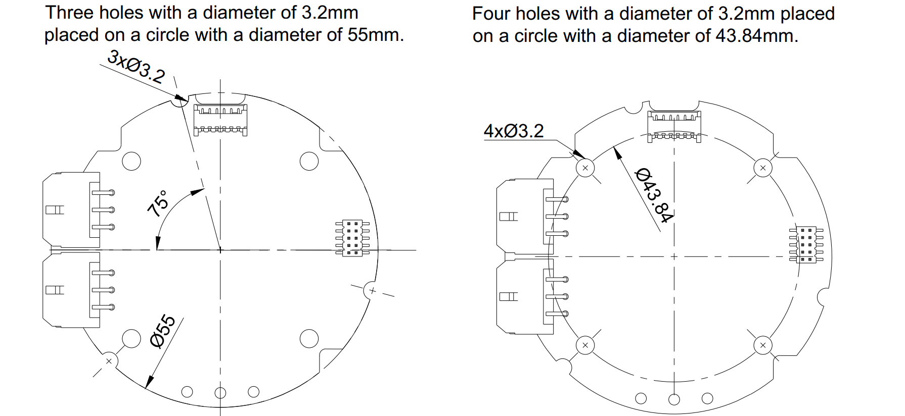
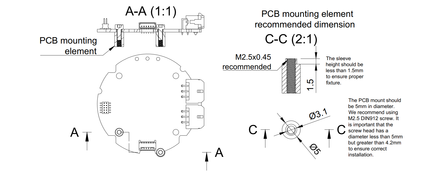
MD80 V3.0 is equipped with seven mounting holes. Please refer to the technical drawing below to find out the hole dimensions and their placement. The 3D model of the driver can be found in the downloads section.
Warning
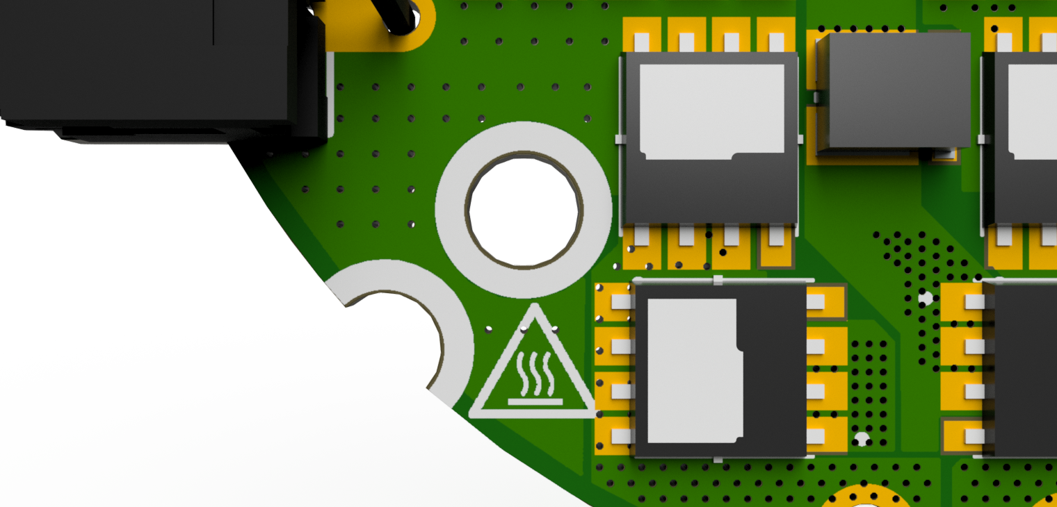
Always make sure the head of the screw is inside the white hole outline. Otherwise, it may cause permanent damage to the controller when a short circuit occurs between the head screw and any of the copper planes. Using M2.5 DIN912 stainless socket screws is recommended.
Solder the motor wires to the PCB making sure all the individual motor wires within a single phase are connected (in case the motor is wound with more than one wire on each phase). It is possible to solder the motor from the bottom, however, soldering the wires on the top is also acceptable. Make sure that the phase wires are connected only to their respective pads.
Warning
The order of the cables does not matter (does not change the rotation direction) as long as the order is not changed after the calibration. Each modification in wire order should be followed by a full motor calibration.
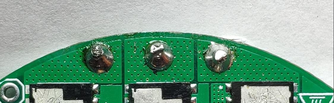
Hint
Sometimes soldering may be difficult due to the high-temperature enamel on the copper wires. In that case, try to apply solder at high temperatures using flux until the solder sticks to all wires nicely.
Connect the power supply to the controller through the CANdle device as specified in this section. When powered the controller should blink shortly with a green LED once a second. If the red LED is fully on there are some errors that should be cleared after the calibration.
Warning
Always make sure that the polarity of the power supply is correct. MD controllers do not have reverse polarity protection so connecting the power supply in reverse polarity will cause permanent damage to the controller.
Connect CANdle to the PC using a USB type-C cable.
Ensure you’ve got the latest MDtool. For the MDtool installation guide refer to the MDtool section.
Please upgrade the setup software if any of your devices (MD or CANdle device) is older than the one from “latest” row in the releases table.
Once installed and run the MDtool will create an MDtool directory in ~/.config directory.
Hint
Press Ctrl+H to view the hidden folders (starting with a dot)
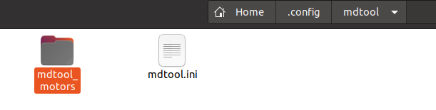
There, you will find a mdtool.ini file which contains factory settings and should not be modified, and a mdtool_motors directory, which holds all the motor configuration files you will work with.
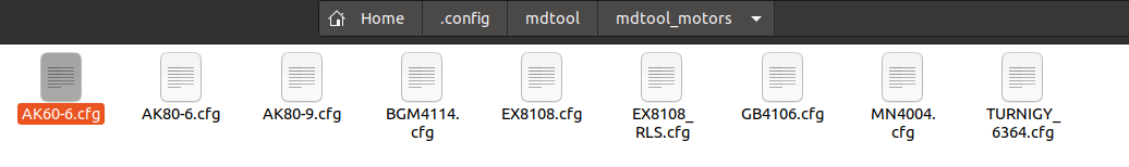
Feel free to add a new *.cfg file for your custom motors in there. Use the already existing files as a reference, especially the AK60-6.cfg which contains some additional comments.
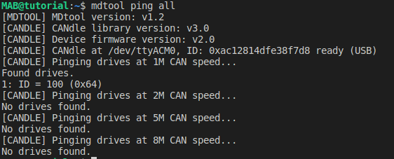
Check if the MD controller can be discovered properly using the
mdtool ping allcommand
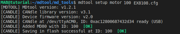
To setup the MD series controller simply call
mdtool setup motor <ID> <*.cfg>where the ID is the ID that shows up after themdtool pingcommand is called, and the *.cfg is one of the files existing in the mdtool_motors directory (press tab to list available config files). If anything fails during the process be sure to check your setup and try again.
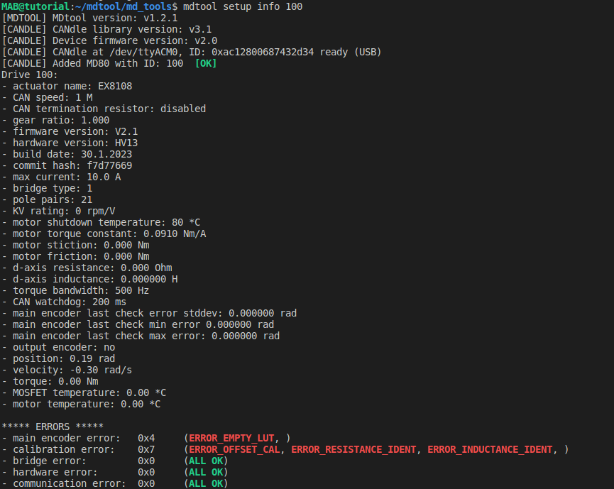
Do not worry if at this point there are many errors after calling
mdtool setup info <ID>command (like below). They should be cleared after a successful calibration.
When succeeded, the motor is set up correctly and now’s the time to calibrate it using
mdtool setup calibration <ID>. Please follow the calibration guidelines for more information on the calibration process itself.After the calibration the motor should be ready to use - the best way to find out everything was completed without errors is to check the MD series motor controller info using the
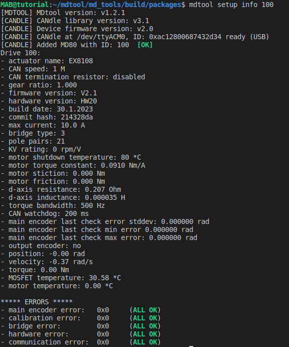
mdtool setup info <ID>. This command lists all the important parameters of the actuator. Errors are shown in red on the bottom if anything has failed during the process. If there are still errors after the calibration be sure to check out the error’s description and try the recommended action to clear it status.
Correct after-calibration mdtool setup info command output may look like this:
Your actuator should be now ready to go! To make it move you can try the mdtool test move <ID> <pos> command, or try the CANdle lib C++ or Python examples.