Motion modes#
Hint
TL;DR: MD80 x CANdle - motion modes
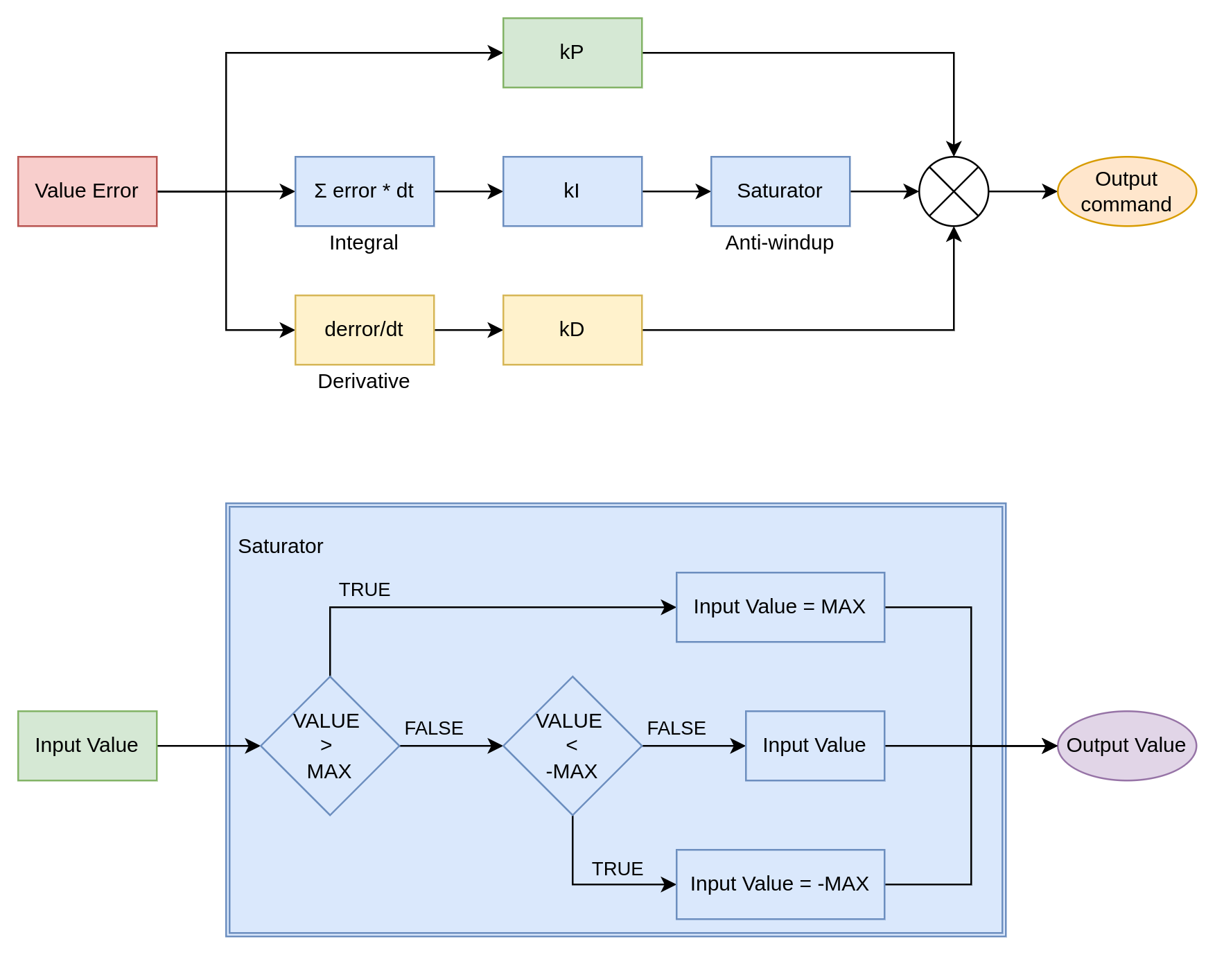
To control the motor shaft with the user’s command MD80 is equipped with multiple control loops. All controllers are based on a regular PID controller design with an anti-windup block. The saturator (anti-windup) is an additional module that acts as a limiter to the ‘I’ part of the controller, as in many systems, the error integration may grow to very large numbers, completely overwhelming ‘P’ and ‘D’ parts of the controller.
Velocity PID#
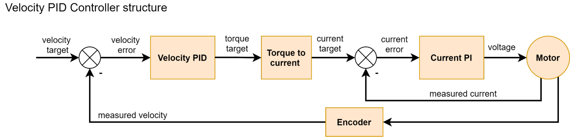
Velocity PID controller calculates velocity error based on target velocity (set by user) and estimated velocity read from the encoder. Its output is a torque command for the internal current/torque controller. The parameters of the controller are:
Velocity Target (in [rad/s])
kP (proportional gain)
kI (integral gain)
kD (derivative gain)
I windup (maximal output of an integral part in[Nm])
Position PID#
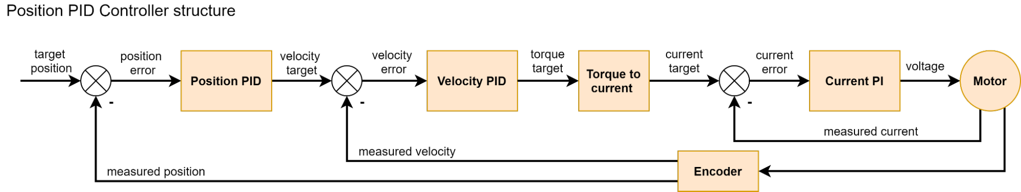
Position PID mode is the most common controller mode used in industrial servo applications. In MD80, it is implemented as a cascaded PID controller. This means that the controller is working in two stages, firstly the position error is calculated, and it is then passed to the Position PID, which outputs the target velocity. This value is then passed as an input to the Velocity PID controller, which outputs commanded torque. This mode uses both Position PID and Velocity PID and thus needs the following parameters:
For Position PID:
Position Target (in [rad])
kP (proportional gain)
kI (integral gain)
kD (derivative gain)
I windup (maximal output of an integral part in [rad/s])
For Velocity PID:
Velocity Target (in [rad/s])
kP (proportional gain)
kI (integral gain)
kD (derivative gain)
I windup (maximal output of an integral part in[Nm])
To properly tune the controller, it is recommended to first tune the velocity controller (in velocity PID mode), and then the position PID. The controller can be described with a diagram:
Impedance PD#
Impedance Control mode is a popular choice for mobile or legged robots, as well as for any compliant mechanism. The main idea behind it is to mimic the behavior of a torsional spring with variable stiffness and damping. The parameters of the controller are:
Position Target
Velocity Target
kP (position gain)
kD (velocity gain)
Torque Feed Forward (Torque FF)
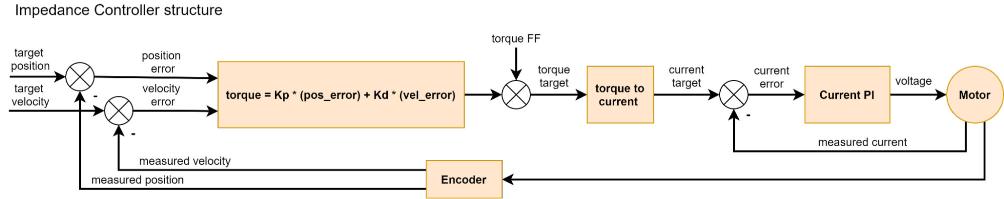
The torque output is proportional to the position error and velocity error and additionally supplemented with a torque command from the user. Here are some of the most common applications for this control mode:
Spring-damper mechanism - when velocity target is set to 0, impedance controllers kP gain acts as the virtual spring stiffness and kD as its damping coefficient. Example use case: a variable suspension for a wheeled robot, where suspension stiffness can be regulated by kP, damping by kD, and height (clearance) by changing the target position;
High-frequency torque controller, where its targets and gains can act as stabilizing agents to the torque command. Example use case: In legged robots, force control can be achieved by advanced control algorithms, which usually operate at rates below 100 Hz. It is usually enough to stabilize the robot but too slow to avoid vibrations. Knowing desired robot’s joint positions, velocities, and torques, drives can be set to produce the proper torque and hold the position/velocity with small gains. This would compensate for any high-frequency oscillations (vibrations) that may occur, as the impedance controller works at 40kHz (much faster than <100 Hz).
Raw torque controller - when kP and kD are set to zero, the torque_ff command is equal to the output controller torque.
The impedance controller is relatively simple and works according to the schematic below:
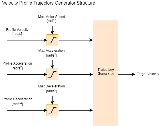
Velocity Profile#
The velocity profile motion mode uses trapezoidal velocity profiles to achieve smooth velocity changes with predefined acceleration and deceleration. The trajectory generator module interpolates between two velocity setpoints to achieve constant acceleration.
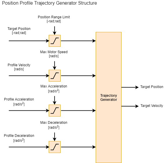
Position Profile#
The position profile motion mode uses trapezoidal velocity profiles to achieve smooth position changes with predefined acceleration, deceleration, and velocity. The trajectory generator module interpolates between two position setpoints to achieve constant acceleration, and linearly changing velocity.
Controller implementation#
Controller implementation can be useful for simulating the actuators in virtual environments. Please find the PID and impedance C/C++ language implementations below:
float mab_controller_performPid(PID_controller *c, float act_value)
{
	c->error_last = c->error;
	c->error = c->target - act_value;
	c->integrator += c->error*c->dt;
	c->integrator = mab_commons_range(c->integrator, -c->integrator_windup, c->integrator_windup);
	c->de = (c->error - c->error_last)/c->dt;
	c->output = mab_commons_range( (c->kp * c->error + c->ki * c->integrator + c->kd * c->de) , -c->output_max, c->output_max);
	return c->output;
}
float mab_controller_performImpedanceController(Impedance_controller *c, float position, float velocity)
{
	c->output = c->setTorque + c->kp * (c->positionTarget - position) + c->kd * (c->velocityTarget - velocity);
	c->output = mab_commons_range(c->output, -c->outputMax, c->outputMax);
	return c->output;
}
Motion controller tuning#
Hint
The best way to get started with tuning is to copy the default gains and tweak them. You can treat this section as our recommendation for tuning the controllers, but online articles can be useful as well
The first step to correctly set up the gains is to start with our default gains. There are three sets of default gains that are set on each motor power up and thus they allow for restoring the actuator to a default state in case some gains were set incorrectly by the user. These gains are also a great starting point for user modifications when the actuator has to be used in a specific application requiring high positioning accuracy or very dynamic movements.
Note
Default gains are set to work with CANdle examples. This way they can be assumed to be universal but it does not have to always be the case
Hint
When something does go wrong during the tuning process just power-cycle the actuator - the default gains will be restored.
Warning
Always keep your safety limits low when experimenting with gains. Gains not suitable for your system may cause oscillations and unstable operation of the MD80-based actuators
Velocity PID / Velocity Profile#
Start by slowly increasing kp gain of the controller keeping ki kd and iWindup set to zero
increase set iWindup to 1.0 and try increasing ki to see if it helps to reach the setpoint velocity
Generally try to avoid using kd
Position PID / Position Profile#
Tune the Velocity PID first - make sure in Velocity PID mode the actuator is able to follow the setpoints
Start by slowly increasing kp gain of the position controller keeping ki kd and iWindup set to zero
Increase set iWindup to 1.0 and try increasing ki to see if it helps to reach the setpoint velocity
Generally try to avoid using kd
Impedance PD#
Increase kp to the point you’re satisfied with the stiffnes of the output shaft (the spring coefficient)
Increase kd to the point youre satified with the damping of the output shaft (the damping coeficient)
Avoid setting kd too high - it may cause severe vibrations.
Current PI#
Current/torque PI is the lowest-level controller. Its gains are not directly user-configurable, however, they can be modified using the bandwidth parameter. Please see the calibration section for more insight on the topic.