Brake Systems#
Introduction#
The MAB SLIM is a series of ultra thin brake systems designed for mobile robotics applications. Brakes are holding when power is off, relieving motors from power consumption on holding static loads. The series is compatible with MD Series drivers controllers and has to be used as a MD add-on in a form of the MAB brake controller (MBC). Brakes can operate in 24-60VDC power supply range and their modularity allows for choosing a holding torque from a wide range of 0.06-38 Nm.
For more information on picking particular brake for your application see our product page here.
MBC#
MD Brake Controller is a device dedicated to control MAB SLIM Electromagnetic Brakes via PWM controlled signal provided by MD board.
ABSOLUTE MAXIMUM RATINGS#
Characteristic |
Rating |
Unit |
Notes |
|---|---|---|---|
Supply Input Voltage |
60 |
V |
|
Control Logic Input Voltage |
24 |
V |
|
Brake Circuit Current |
2.3 |
A |
at 25°C |
Ambient Temperature |
80 |
°C |
|
Duty Cycle |
90 |
% |
Electrical Characteristic#
Characteristic |
Rating |
Unit |
Notes |
|---|---|---|---|
Nominal Supply Input Voltages |
24/48 |
V |
|
Nominal Control Logic Voltage |
3.3 |
V |
|
Typical PWM Frequency |
20 |
kHz |
at 10%-90% fill |
Logic Input Current |
7 |
mA |
at 3.3V |
Mechanical Specification#
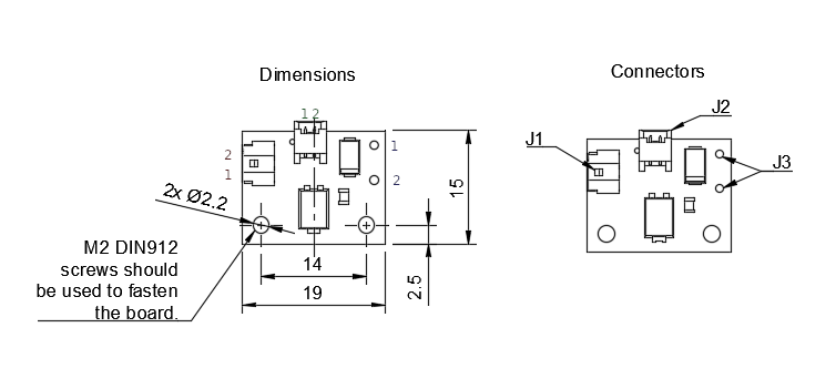
The board can be fastened in place using 2 mounting points with M2 DIN 912 screws.
Functional Description#
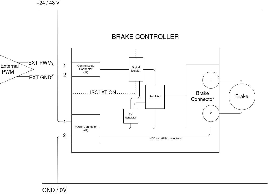
The product has an open-drain output in the form of two solderable pads (J3) for control of the brake state. Output’s state is directly controlled via input PWM signal provided on the pin 1 of the control logic connector (J2) with return path provided on pin 2.
Output state is high-impedance when the PWM pin is set low. Low-impedance when the PWM pin is set high.
Logical controls are galvanically isolated from the power circuitry, unless the jumper JP1 is soldered.
Connection and Integration of SLIM#
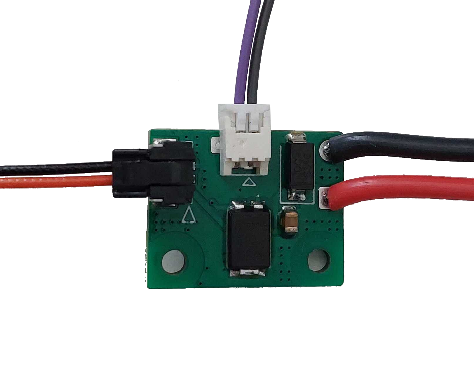
TODO: change photographs here
With each shipping of MBC and SLIM brake we include necessary wiring:
Power cable (10 cm) - Red and Black wire pair ending with a black J1 connector are intended power supply for the brake. It can be provided via external tri-connectors or directly from power supply.
PWM signal cable (10 cm) - Green and Brown wire pair ending with a white J2 connector connect to the 8-pin header on the MD boards.
Brakes come with wires already integrated.
Note
When there is no space for external connection of power there is a possibility to solder the power wires directly onto the MD board, however this is not recommended.
Important
The power supply voltage must be the same as MD’s in order for the MBC to operate correctly with the MD.
Note
MD utilizes GPIO B of its connector to generate PWM signal so it is always utilized by the board when external brake is enabled. However, if there is a necessity to utilize the 8-pin connector for other purposes, such as a RLS encoder, the GND signal from this connector can be disconnected. This requires the jumper at the bottom of the MBC to be soldered in closed position. It eliminates galvanic isolation between the MCU signal and coil connector which in over-current scenarios can possibly destroy the driver.
In order for the MD to utilize SLIM system the driver must be properly configured. See GPIO and User Gpio Configuration register section for more details.