Output Encoder#
Output encoder is a position sensor that can be attached to the output shaft of the actuator. It is usually useful for geared motors where the output shaft position after startup cannot be determined unambiguously using the MD’s onboard encoder due to the gearbox. By using an output encoder one can make sure that the output shaft position is always known at startup.
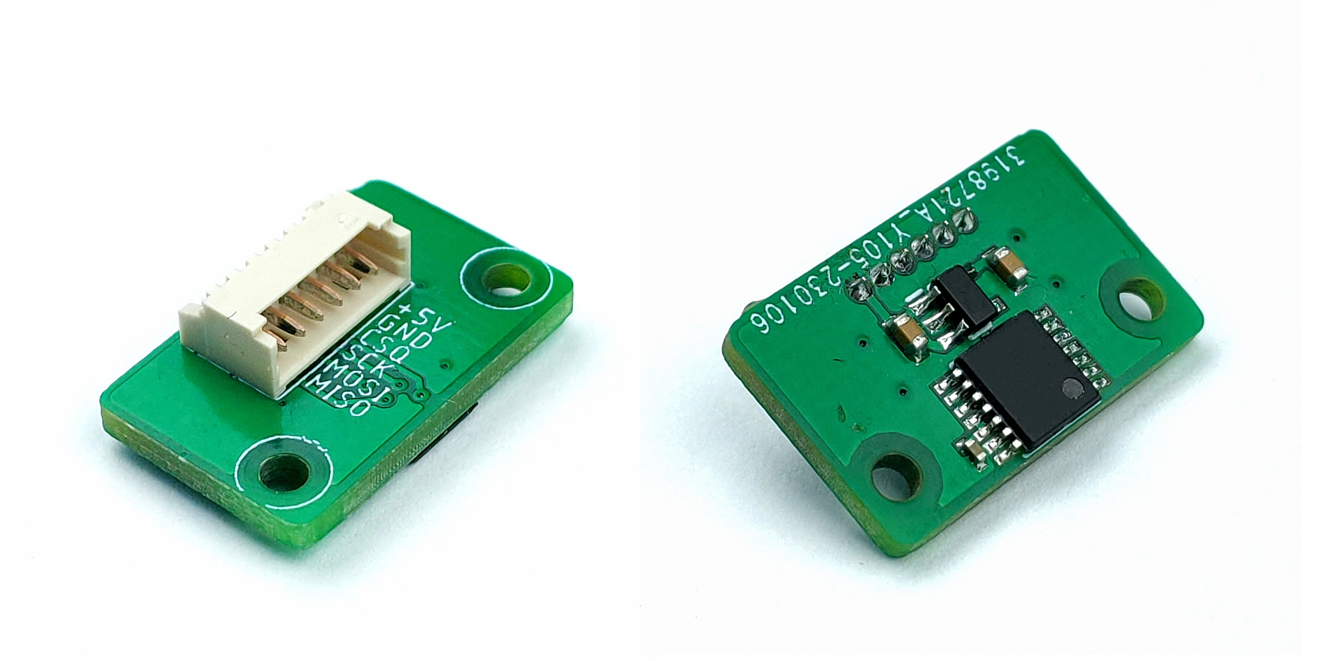
Currently we support one encoder type with two placement configurations:
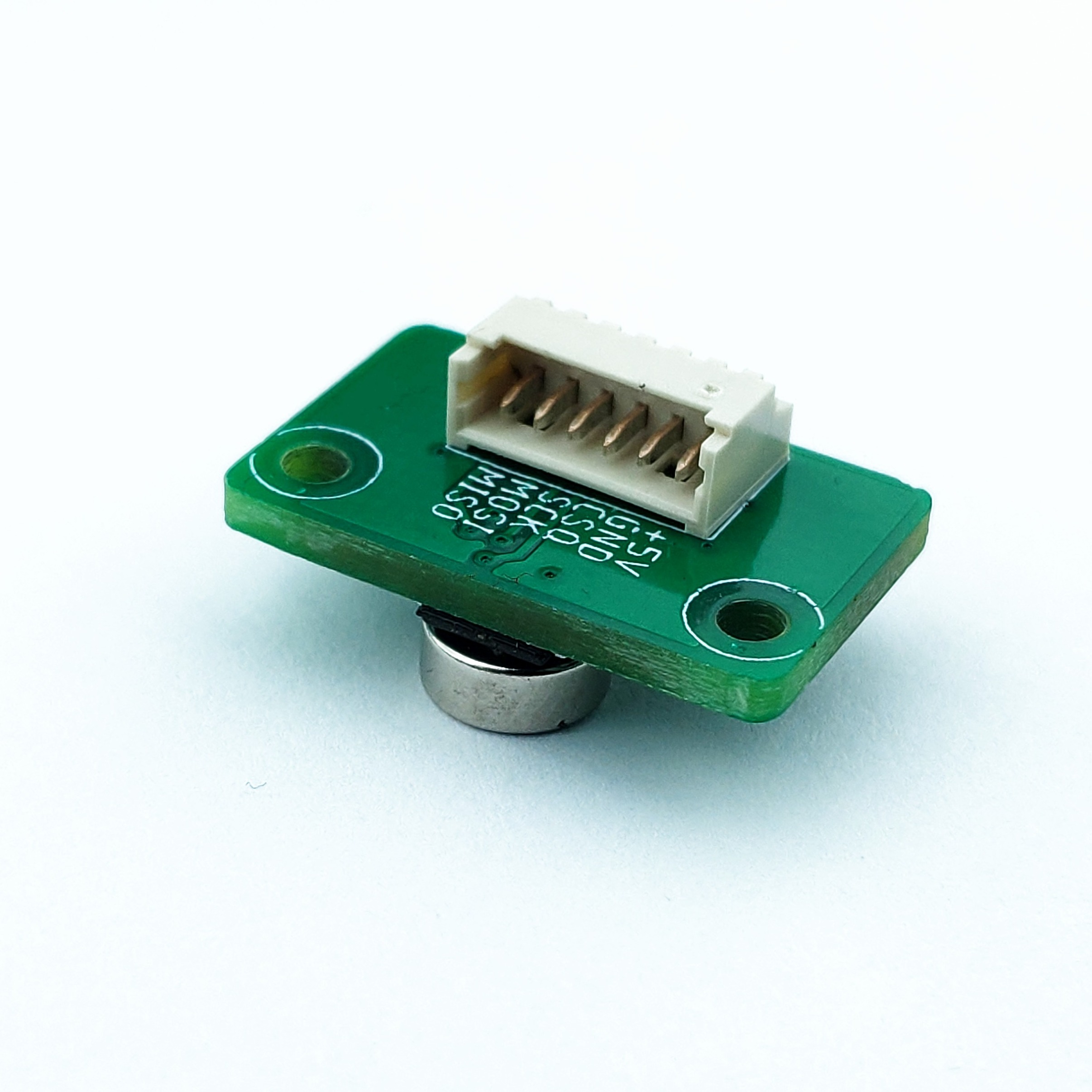
ME AS placed axially on the output shaft with a regular diametrically magnetized magnet
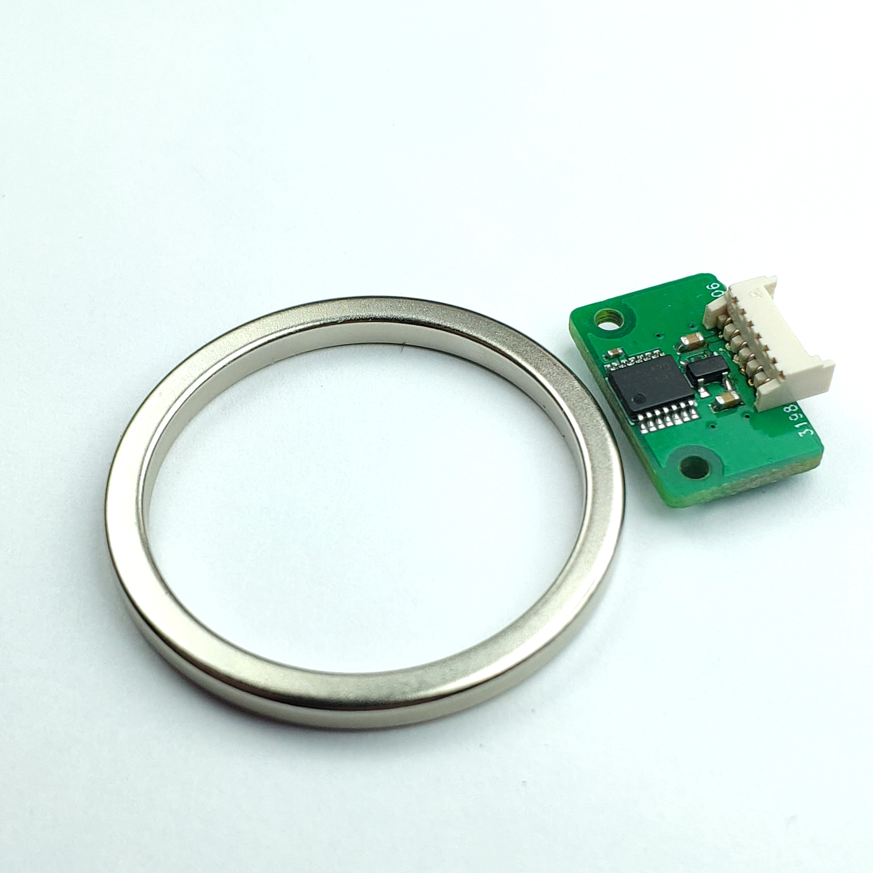
ME AS placed non-axially together with a diametrically magnetized ring magnet
Configuration#
The output encoder configuration is performed in the motor config files and saved to the MD series motor controller using the mdtool setup motor command. There are only two parameters used in output encoder setup:
[output encoder]
output encoder = <encoder type>
output encoder mode = <encoder mode>
where:
<encoder type> |
Description |
|---|---|
ME_AS_CENTER |
for axially placed ME AS encoder |
ME_AS_OFFAXIS |
for non-axially placed ME AS |
MB053SFA17BENT00 |
Renishaw RS422 17-bit RLS encoder |
CM_OFFAXIS |
CubeMars motors offaxis encoder |
<encoder mode> |
Description |
|---|---|
STARTUP |
initial position from output encoder, report main encoder values, motion based on main encoder |
MOTION |
initial position from output encoder, report output encoder values, motion based on output encoder |
REPORT |
initial position from main encoder, report output encoder values, motion based on main encoder, calibration of the output encoder is impossible |
MAIN |
output encoder is used as the main encoder. All output encoder measurements are mapped as main encoder values. |
CALIBRATED_REPORT |
initial position from main encoder, report output encoder values, motion based on main encoder, calibration of the output encoder is possible |
Warning
The non-axial configuration outputs a nonlinear position values. This means it requires a full calibration (your setup should be able to rotate by at least one full rotation), and in case of the report mode it will output nonlinear position and velocity readings that will have to be compensated in the host’s software
Not all modes are recommended for every encoder. The non-axially placed ME AS encoder is inherently more noisy and less accurate and thus we recommend using it only in STARTUP mode. Please refer to the table below:
<encoder type> |
Valid modes |
Description |
|---|---|---|
ME_AS_CENTER |
STARTUP / MOTION / REPORT / MAIN / CALIBRATED_REPORT |
- |
ME_AS_OFFAXIS |
STARTUP |
This configuration is much more noisy than the axial placement |
MB053SFA17BENT00 |
STARTUP / MOTION / REPORT / MAIN / CALIBRATED_REPORT |
- |
CM_OFFAXIS |
STARTUP |
Only offaxis configuration is supported |
Steps to add an external encoder to the driver setup:
make sure the encoder sensor is placed correctly:
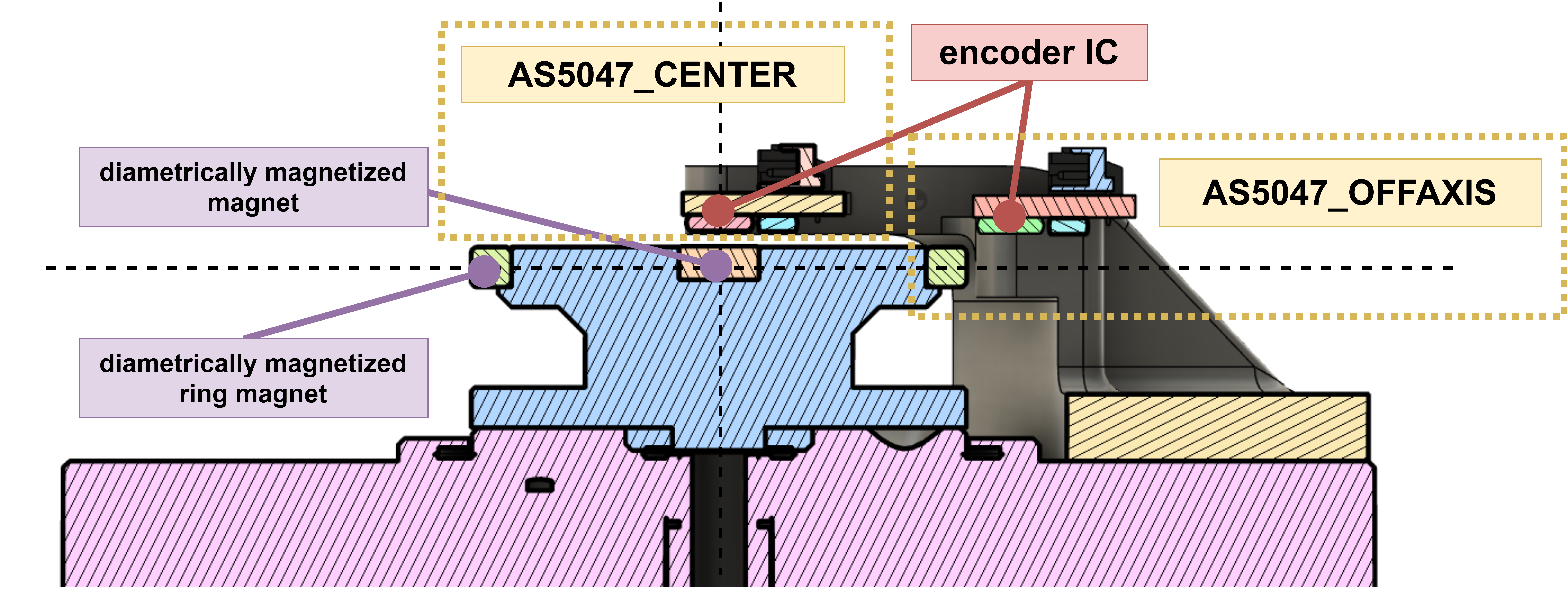
in case of axially placed sensors make sure they are placed in center at correct height above the magnet (1 mm is usually optimal)
in case of non-axial configuration make sure the magnet is close to the ring magnet (<0.5mm) and the sensor IC is at least 2mm above or below the ring magnet horizontal plane.
Connect the MDxx with the encoder using a picoblade series cable assembly and connect power to the MDxx.
Modify the motor config file according to your setup and save it to the MDxx using mdtool

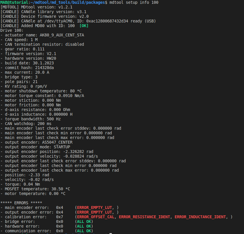
You can confirm the setup using the mdtool setup info command to make sure all parameters are correct:
Note
At this point some errors will be present as the setup is not yet calibrated.
Calibrate the MDxx using
mdtool setup calibrationcommandCalibrate the output encoder using
mdtool setup calibration_outcommandTest the encoders using
mdtool test encodercommand.Use the
mdtool setup info allcommand to make sure there are no errors and the test results (min, max and stddev errors) are within your expectations.The external encoder is ready to use! For more information on external encoder parameters please see the output encoder calibration section.
