MD80#
General parameters#
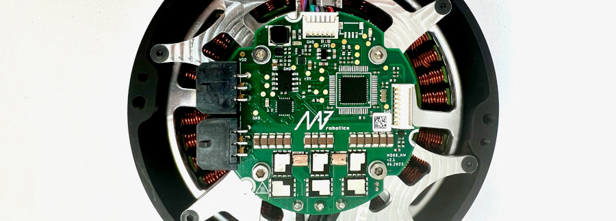
MD80 is a brushless motor controller. It can work with a variety of motors and reducers that can be precisely matched to the users’ specifications. All MD80 variants are using an advanced motor control algorithm (FOC), a high-resolution encoder, a high-speed FDCAN communication bus, and a common communication interface. The controller features position PID, velocity PID, impedance, profile position and profile velocity operation modes. MD80 can be easily daisy-chained, for easy connection of many drives in a single control network.
General parameters table for MD80 V3.0+:
Parameter |
Value |
|---|---|
Nominal Input Voltage Range |
24 - 42 VDC |
Maximum Input Voltage Range |
10 - 48 VDC |
Max Input Current (connector) |
10.0 A (RMS) |
Max Continuous Phase Current w/o cooling |
20 A |
Max Peak Phase Current (t = 2 s) |
80 A |
Built-in software-controlled termination resistor |
optional |
FDCAN Baudrate (adjustable) |
1/2/5/8 Mbps |
Position PID Controller Execution Frequency |
1 kHz |
Velocity PID Controller Execution Frequency |
5 kHz |
Impedance Controller Execution Frequency |
40 kHz |
Torque Control Execution Frequency |
40 kHz |
Torque Bandwidth (adjustable) |
50 Hz - 2.5 kHz |
External encoder support |
yes, SPI and RS422 (optional) |
External 5V power supply max current |
150 mA |
Warning
MD80 is not suited for working on 12S lithium batteries, as their fully charged voltage exceeds maximum input voltage. MAB recommends to use MD80 with up to 10S batteries, for safe and reliable operation. For 12S and bigger batteries, please refer to MD80 60V, that can operate up to 60V.
General parameters table for MD80 HW1.1, HV1.3 and older:
Parameter |
Value |
|---|---|
Input Voltage |
18 - 28 VDC |
Nominal Input Voltage |
24 VDC |
Max Input Current (RMS) |
10 A |
Max Continuous Phase Current |
20 A |
Max Peak Phase Current (t = 4 s) |
40 A |
FDCAN Baudrate (adjustable) |
1/2/5/8 Mbps |
Position PID Controller Execution Frequency |
1 kHz |
Velocity PID Controller Execution Frequency |
5 kHz |
Impedance Controller Execution Frequency |
40 kHz |
Torque Control Execution Frequency |
40 kHz |
Torque Bandwidth (adjustable) |
50 Hz - 2.5 kHz |
Mechanical integration#
Candletool can be used to set up a new motor to work with the MD series motor controller controller. More information on that can be found in Getting Started section.
First, make sure the MD controller can work with your motor. A vast majority of hobby motors will be suitable, although too big motors in terms of power and gimbal motors ( with high phase resistance) might not work as expected. Be sure to contact us before you proceed with a gimbal or high-power motor (over 500W peak power).
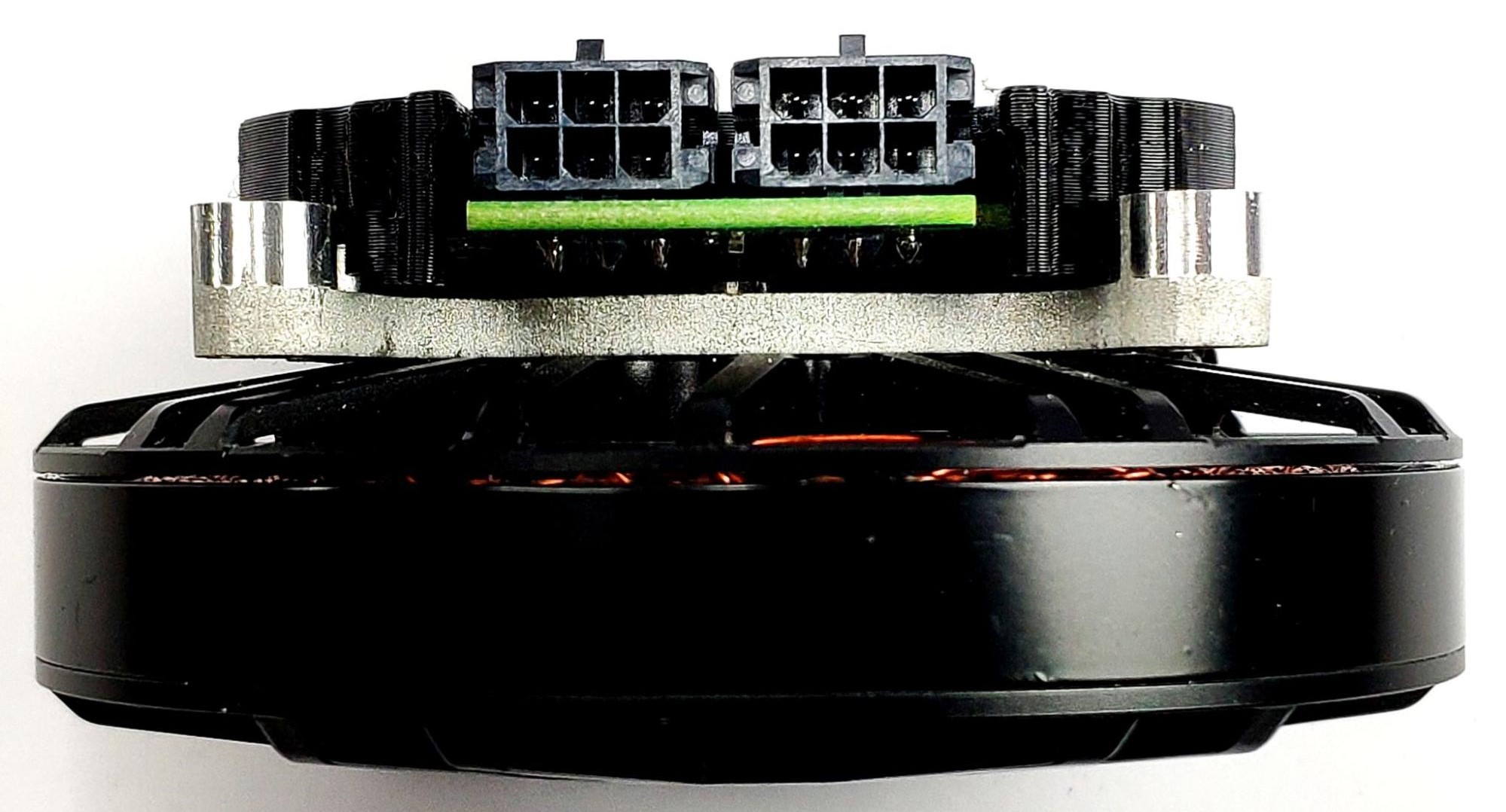
Place the diametrically magnetized magnet on the motor shaft and mount the MD controller firmly, centered above the magnet.
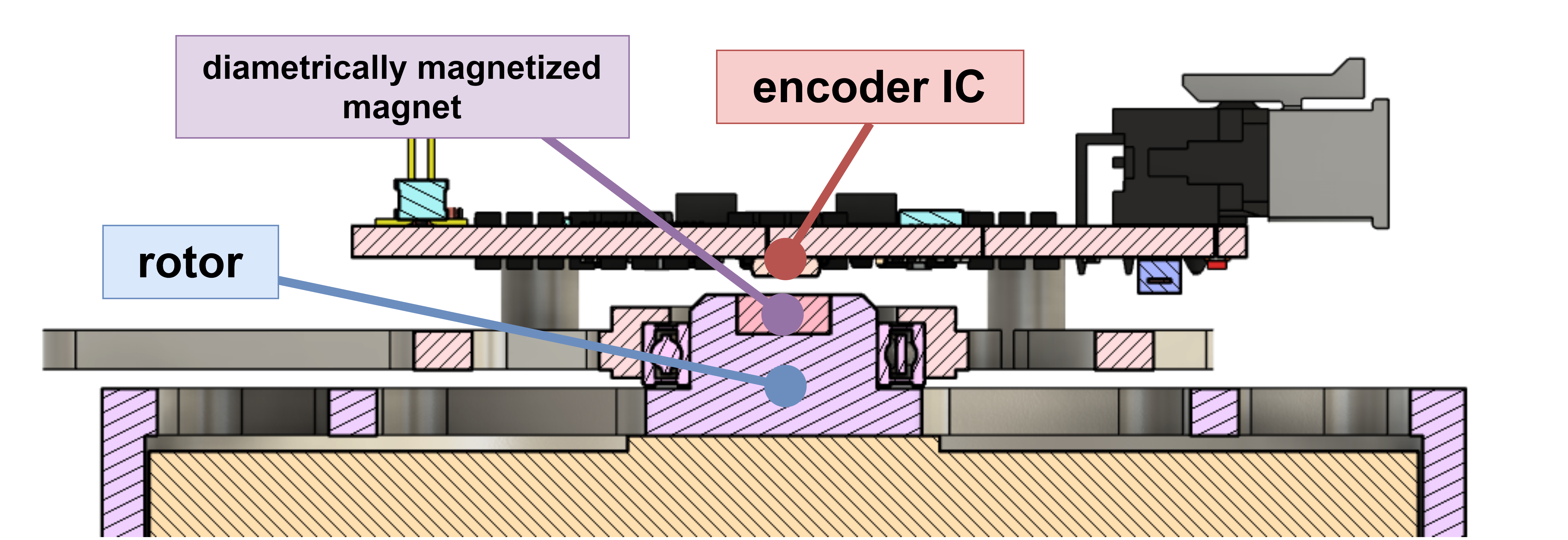
Fig. 1 Magnet - encoder placement cross section#
The optimal height between the magnet and the encoder IC is 1mm. The magnet and the encoder must be on the same rotation axis.
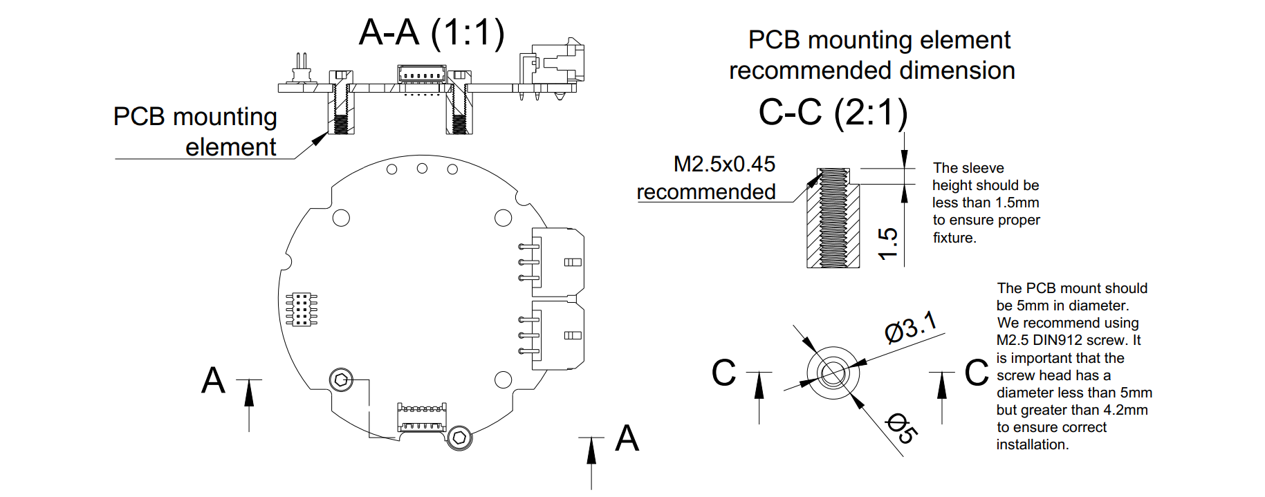
MD80 V3.0 is equipped with seven mounting holes. Please refer to the technical drawing above to find out the hole dimensions and their placement. The 3D model of the driver can be found in the 3D models gdrive directory.
Warning
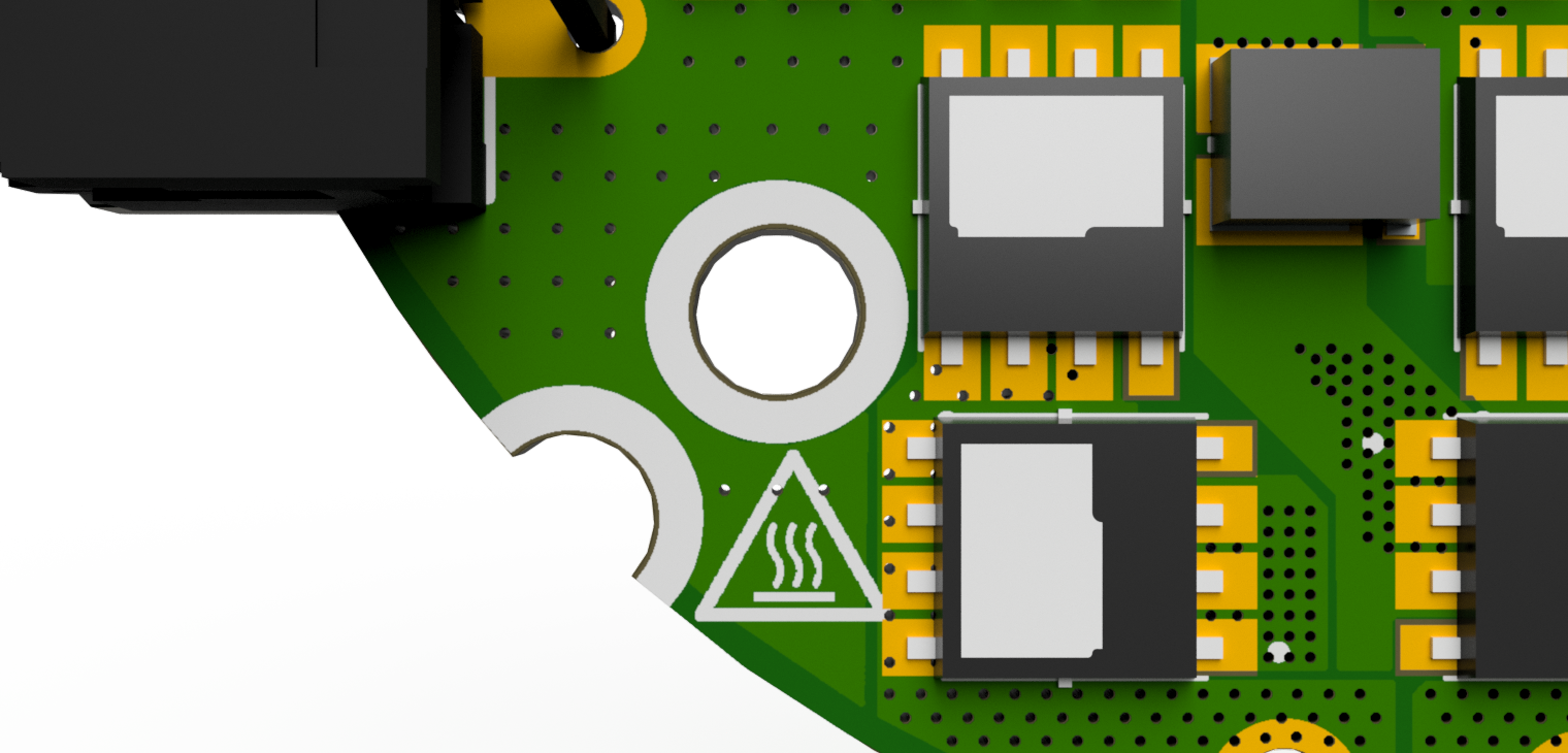
Always make sure the head of the screw is inside the white hole outline. Otherwise, it may cause permanent damage to the controller when a short circuit occurs between the head screw and any of the copper planes. Using M2.5 DIN912 stainless socket screws is recommended.
Solder the motor wires to the PCB making sure all the individual motor wires within a single phase are connected (in case the motor is wound with more than one wire on each phase). It is possible to solder the motor from the bottom, however, soldering the wires on the top is also acceptable. Make sure that the phase wires are connected only to their respective pads.
Warning
The order of the cables does not matter (does not change the rotation direction) as long as the order is not changed after the calibration. Each modification in wire order should be followed by a full motor calibration.
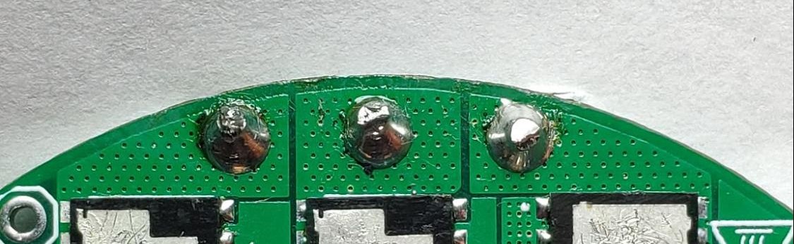
Hint
Sometimes soldering may be difficult due to the high-temperature enamel on the copper wires. In that case, try to apply solder at high temperatures using flux until the solder sticks to all wires nicely.
Connect the power supply to the controller through the CANdle device. When powered the controller should blink shortly with a green LED once a second. If the red LED is fully on there are some errors that should be cleared after the calibration.
Warning
Always make sure that the polarity of the power supply is correct. MD controllers do not have reverse polarity protection so connecting the power supply in reverse polarity will cause permanent damage to the controller.
Connectors pinout#
The connectors used in the system on the CAN FD side are MOLEX Micro-Fit series 3.0. Both connectors are connected in parallel for easy daisy-chaining. The connector pinout with respected color coding is presented below:
Warning
Always make sure CAN bus lines are not shorted to the positive power rail. Applying supply voltage to these pins will cause permanent damage to the controller!
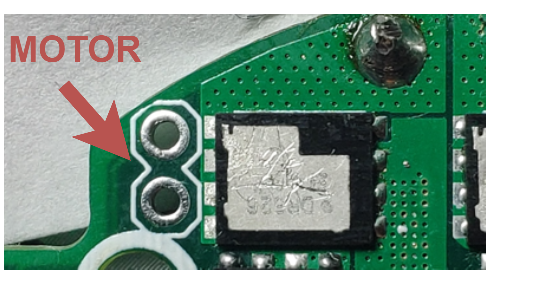
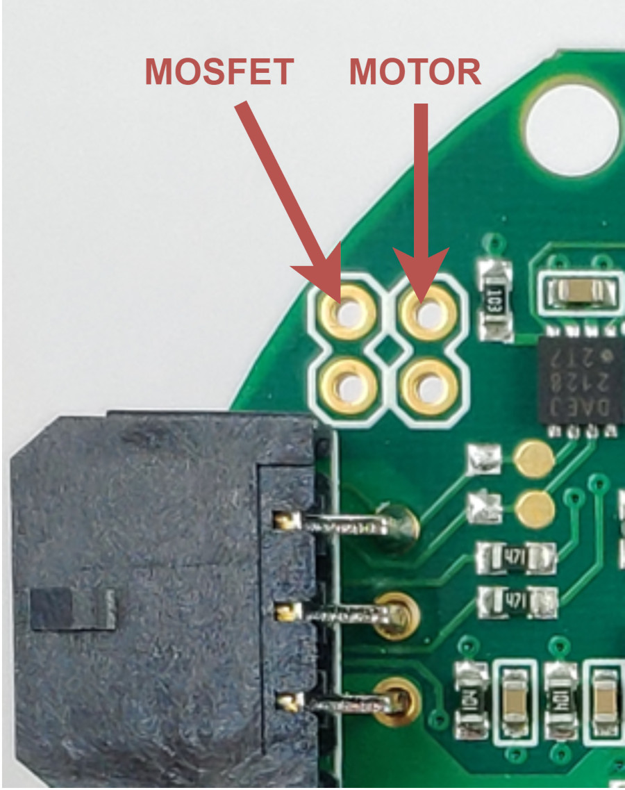
Thermistor connection#
All MD80 versions have the capability to measure the MOSFET and motor temperature. This is to ensure the safe operation of the driver and motor. The motor shutdown temperature is configurable up to 140°C max with a hysteresis of 20°C. The driver shutdown temperature is fixed at 100°C with a hysteresis of 20°C. MOSFET thermistor is built-in directly under the power stage and only the motor thermistor connector is available:
Older MD80 revisions (1.1, 1.3, 2.0 and 2.1)
On older (<HW2.2) designs NTCMHP100K is recommended as thermistor. On 1.1 and 1.3 revisions, thermistors are to be connected as follows:
Note
For modern MD80 (2.2+), we recommend using MABs thermistors. Using other thermistors may result in imprecise temperature readout.
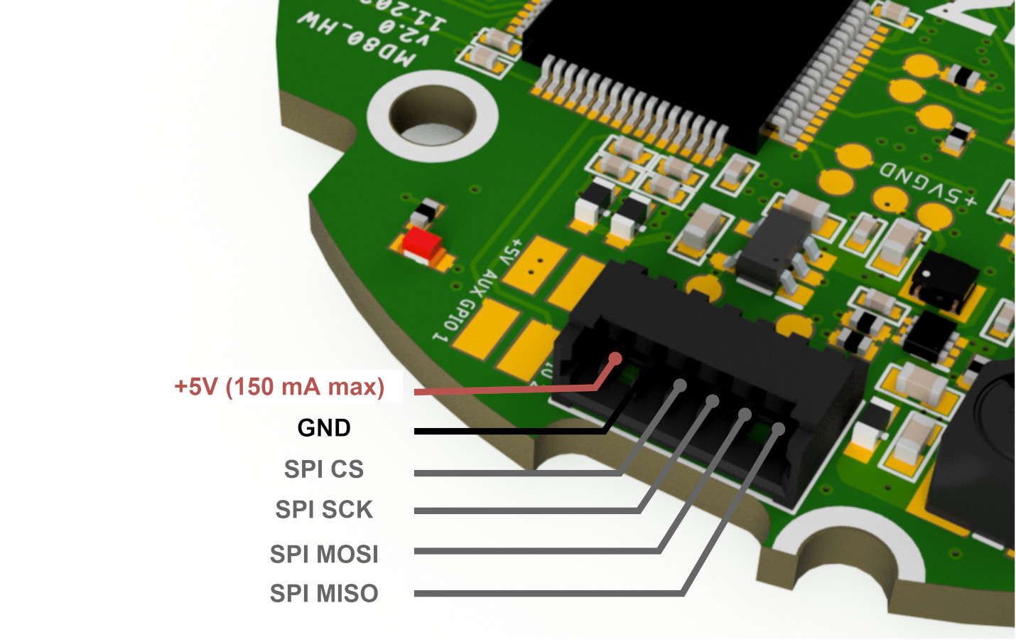
Aux connectors#
MD80 2.1 and newer feature two accessory connectors.
Aux 1 connector is dedicated to connect MABs ME_am and other SPI based encoders. For external encoder connection via the SPI 530480650 Molex PicoBlade connectors is provided.
Warning
While auxiliary connector pins are 5V tolerant, we recommend using 3.3V logic if possible.
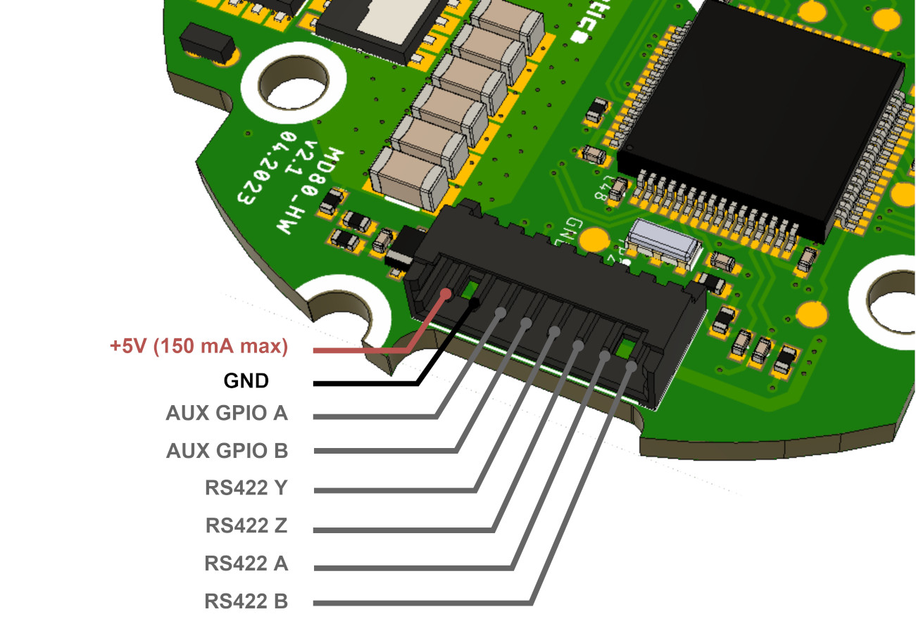
Aux 2 connector has two user-configurable GPIOs, and RS422 interface for connecting to RLS Axim2
encoder. AUX GPIO A pin can be used as an automatic brake control output signal. This signal when
amplified, can be used to control
MAB SLIM electromagnetic
brakes. Enabling of this mode is done via userGpioConfiguration register. When enabled driver will
automatically disengage the brake when enabled. For external encoder connection via the RS422 and
the GPIO pins utilization 530480810 Molex PicoBlade connectors could be used.
We are able to integrate custom functions such as GPIOs for external sensors and indicators. For more information please contact us: contact@mabrobotics.pl
Warning
By default RS422 transceiver is not soldered on the MD80 boards. If you plan to use RLS Axim2 encoder with MD80, let us know when ordering the board. This modification will be done free of charge.
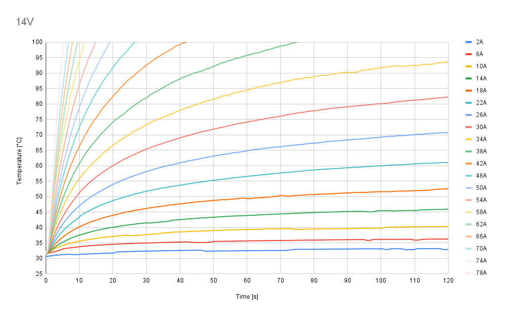
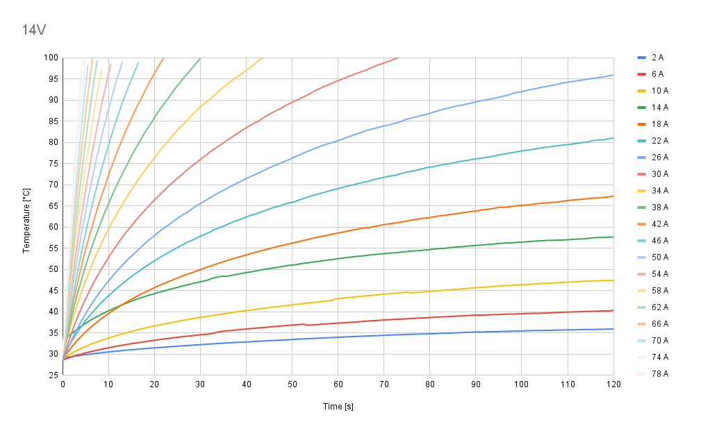
Thermal characteristics#
Test Conditions and Setup
To cover all potential cases, three cooling scenarios have been performed:
No additional cooling
Passive cooling
Active air cooling
MD80 driver was tested using coupled inductors (each 22uH) - simulating a motor.
The circuit of the test station is visible below.

In this way driver is set up for the worst case when there is no shaft and all the power is converted to heat.
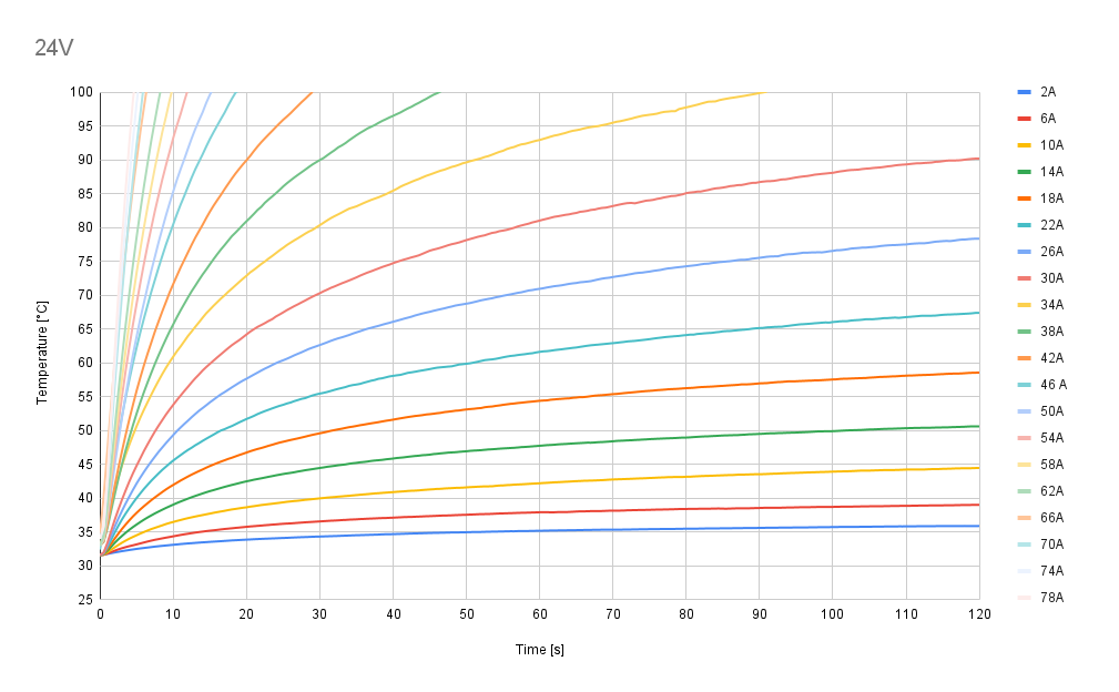
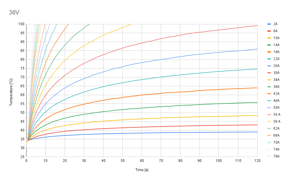
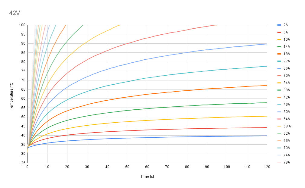
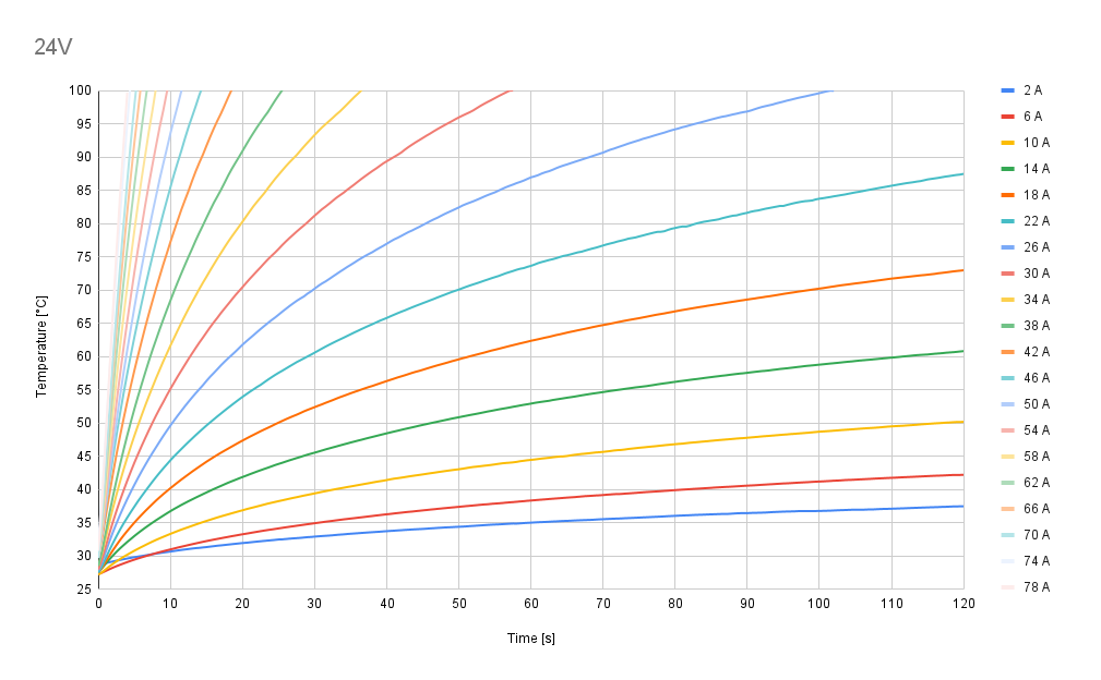
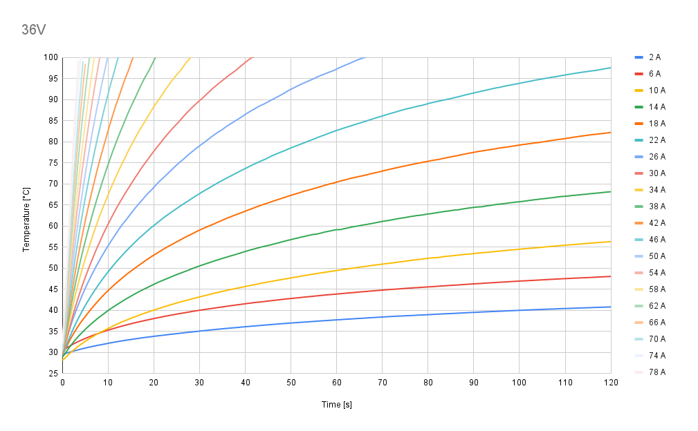
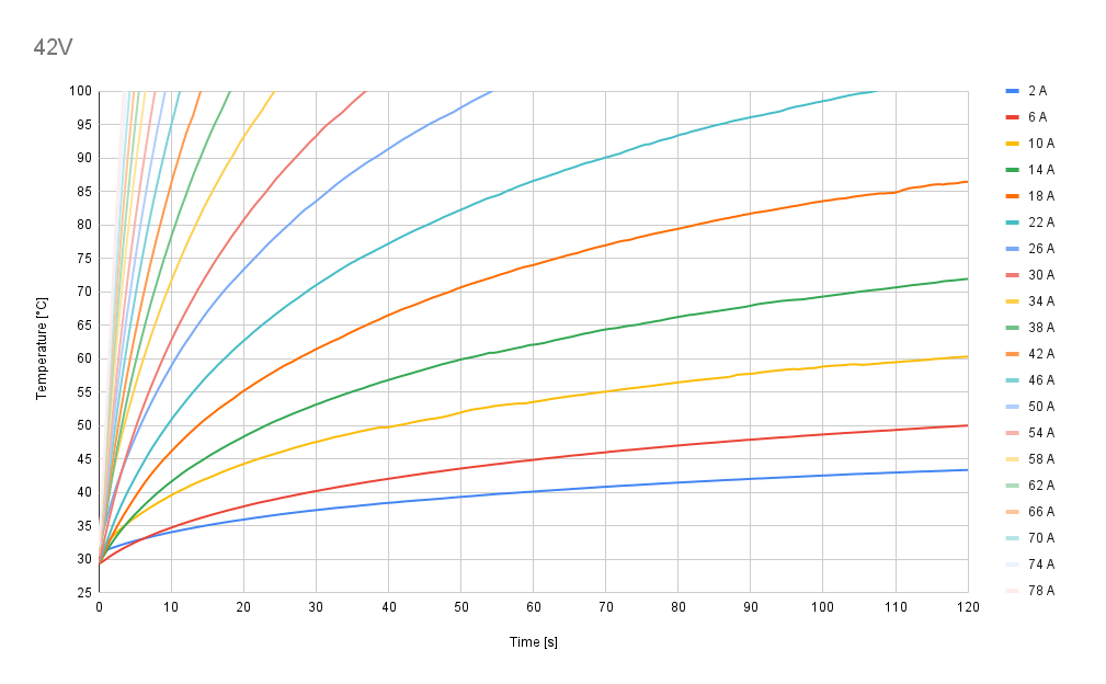
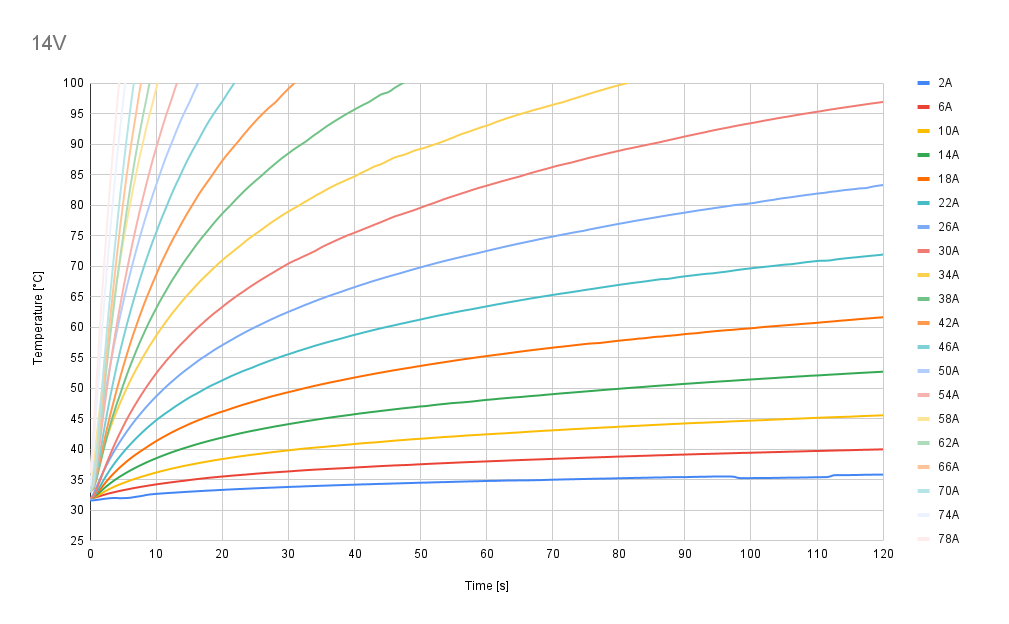
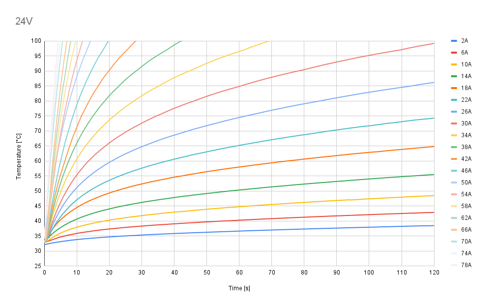
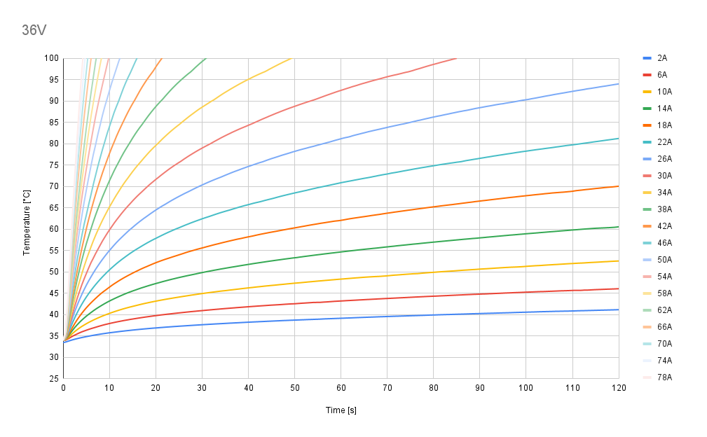
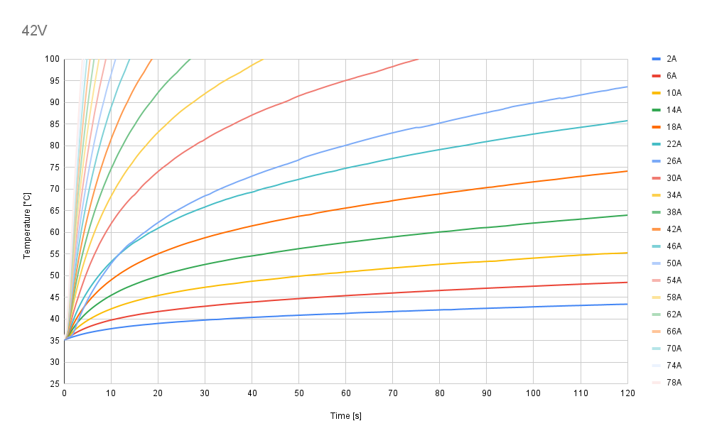
In each scenario, tests were conducted for a range of phase currents, varying from 2 A to 78 A in 4 A increments. For each current level, the setup was operated until the temperature stabilized, with a target duration of 120 seconds.
All tests were performed in constant environment conditions, in still air at 25°C ambient temperature.
The temperature was measured using an onboard thermistor placed on the bottom layer of the PCB, directly below the MOSFETs.
Tests were performed using voltage levels of 14V, 24V, 36V and 42V.
Test scenario I - no cooling
Test scenario II - passive cooling
Test scenario III - active air cooling