Measurements#
MD drivers are equipped with sensors that allow for measuring the motor position, velocity, and torque. Whether the motor has an integrated gearbox or not, the position, velocity, and torque are in the output shaft reference frame. This means that changing the position from 0.0 to 2\(\\pi\) radians, will result in approximately one rotation of the motor for direct-drive (gearless) servos and approximately one rotation of the gearbox output shaft for geared motors.
Position#
To measure the position of the rotor the MD driver uses an internal magnetic encoder. The resolution
of the encoder is 14 bits (16384 counts per rotation). The drive aggregates all the measurements to
provide multi-rotation positional feedback. The reference position (0.0 rad) is set by the user
and stored in the non-volatile memory. Please see candletool md zero
command for more information on how to set the desired zero position.
When the actuator power-up, the position readout is clamped to in -PI to +PI rad.
Important
When using geared actuators with gear ratios above 1:1 it is not possible to determine the position after startup unambiguously, since the motor completes multiple rotations per single rotation of the output shaft. For example, for a 2:1 gearbox, there are two sections within a single output shaft rotation where the motor shaft is in the same position. Unless the motor is placed in the wrong “section” during startup the absolute encoder functionality will work. To deal with this issue please see the axu encoder.
Velocity#
The velocity is estimated by measuring position change in time, at a frequency of 40kHz. The measurements are then filtered using a low-pass filter with a cut-off frequency of 5 kHz since the position differentiation method introduces noise.
Torque#
Actuator torque is estimated by measuring motor phase currents. This method can be used on low-gear ratio actuators (preferably below 9:1), that are easily back-drivable, to get an estimate of the torque applied by the motor. In applications with higher gear ratios, the torque readout might be less accurate due to excessive friction in the gearbox.
For applications that require a direct torque measurement independent of gearbox friction, MD also supports connecting an external torque sensor.
Power, input current and motor phase current#
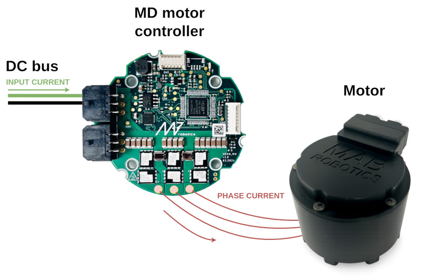
Input current flows from the power supply into the controller. It increases when the motor works harder (more torque, higher speed). Think of it like fuel consumption in a car — the harder you push, the more you burn.
Motor phase current is generated by the MD motor controller and directly determines motor torque. The controller regulates it via a high-frequency FOC loop — more phase current means more torque. Think of the controller as a three-phase DC/DC converter that sets the output current by adjusting the phase voltage through PWM.
This relation can be described with following equantion:
\(P = I_{dc} \cdot U_{dc} = I_{phase} \cdot U_{dc} \cdot \text{PWM}_{duty}\)
In real drive system there are losses which are omitted for simplicity.
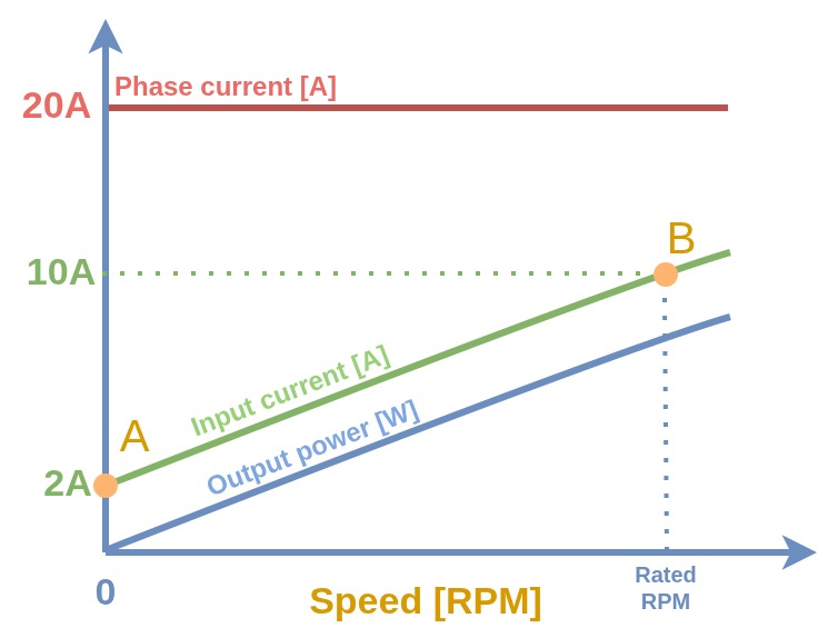
Visual relationship between output power, input current and motor phase current is presented below:
Motor operating conditions: Case A vs Case B#
To illustrate the difference between two distinct motor operating conditions, two points are marked on the graph: A and B.
Case A — holding torque, zero speed#
Parameter |
Value |
|---|---|
Torque / current setpoint |
20 A |
Motor state |
Shaft blocked or heavily loaded |
Speed |
0 RPM |
Input current |
~2 A — covers only system power losses |
Example scenarios:
Actuators in a loaded robotic arm that don’t move,
Actuators in a humanoid robot’s arms during walking while holding objects,
Actuators in a quadruped robot’s legs during standing.
All these scenarios share the same load scheme — significant motor phase current, but no mechanical work done. Energy is lost as heat in the wires, motor controller, power supply, and primarily in the motor coil resistance. Efficiency: 0%.
Case B — active work under load#
Parameter |
Value |
|---|---|
Torque / current setpoint |
20 A |
Motor state |
Heavy load, not blocked — producing torque |
Speed |
50 RPM |
Input current |
~10 A — covers losses and physical work |
Example scenarios:
Actuators in a loaded robotic arm that move quickly,
Actuators in a humanoid robot’s arms during lifting objects,
Actuators in a quadruped robot’s legs during running.