Power Stage#
The PDS_PS module is a high-power power path designed to provide a safe and reliable power source for robot actuators. Its features include:
continuous current capacity of up to 50A,
isolated voltage and current measurements for precise monitoring,
bus-controlled with an electronic high-side switch for efficient power management
inrush current limitation to prevent damage from startup surges,
high-quality bulk capacitance for stable operation,
protection against reverse polarity, over-voltage and over-current to ensure safety,
transient protection for resilience against voltage spikes,
thermal monitoring and safe operation.
Parameter |
Value |
|---|---|
Input voltage |
10–54 V |
Input protection |
Reverse polarity down to –54 V, overvoltage, overcurrent (no fuse on the board, based on current monitoring), transients |
Output current |
up to 50 A |
Delivered power |
up to 2500 W |
Total internal resistance |
1.35 mΩ |
Conduction losses at 50 A current (excluding connector resistance) |
3.375 W |
Power transfer efficiency |
up to 99.8% |
Output protection |
Over-current, over-voltage, over-temperature, transient |
Internal bus capacitance |
282 µF (low ESR Aluminum Hybrid Polymer Capacitors) |
Current consumption on standby (no load) |
11.56 mA |
Quiescent current in shutdown |
1.97 µA |
Mass |
43 g |
Ambient Temperature (Operating) |
0–40 ℃ |
Ambient Temperature (Non-operating) |
0–60 ℃ |
Maximum Humidity (Operating) |
up to 95%, non-condensing at 40 ℃ |
Maximum Humidity (Non-operating) |
up to 95%, non-condensing at 60 ℃ |
Altitude (Operating) |
–400 m to 2000 m |

Fig. 8 Power stage with highlighted ports#
Connector Name |
Included Cable Specification |
Wiring Details |
|---|---|---|
MASTER MODULE |
10-pin Molex PicoBlade |
Connect to control board |
POWER OUTPUT PORT 1/2/3 |
No cables included |
Connect the actuators to Molex Micro-Fit ports |
BRAKE RESISTOR / AUXILIARY POWER SUPPLY |
691340500006 included without cables |
Power output port for brake or actuators. Recommended connectors: 691340500006 or 691343510006. |
Inrush current limitation and hardware thermal protection#
Inrush current is a brief surge of high electrical current that occurs when a device is first turned on, before it settles to its normal operating current. When all connected devices together have high capacitance, it draws a large inrush current when first powered on because the capacitors initially act like a short circuit and pull a big current while charging.
To avoid this we implemented current limitation on start of turning of the PS. The module’s resistors limit the current required to charge the capacitance, preventing devices from experiencing current shock.
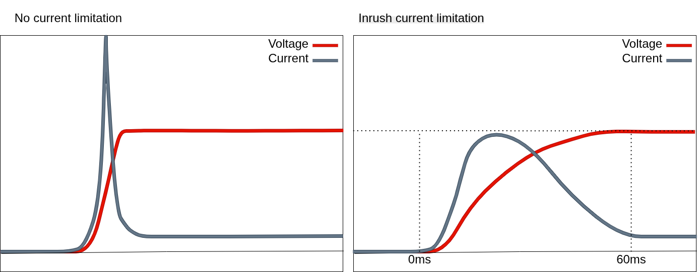
Fig. 9 Inrush comparison visual example#
Device is turned on fully after an additional time, at around 60ms after enabling PS. By this time, PowerStage module can resist to up to 10mF load of capacitance.
Heat generated by the high current is handled by dedicated onboard resistors (2x 5 Ohm). These resistors are paired with hardware thermal protection, which can also protect the entire board if it exceeds safe operating temperatures. Additionally, there is another thermistor close to MOSFETs on the main part of the board.
Over current level and over current delay can be set in PDS configuration file and manually using candletool, see PDS configuration file and candletool for PDS
Important
POWER OUTPUT PORTS 1, 2, and 3 are dedicated to supplying power to actuators and do not support FDCAN communication to the PDS. However, FDCAN connectivity can be shared between MOLEX ports, as illustrated in FDCAN Architecture section.
More information about commands in CANdle-SDK PDS commands and candletool for PDS