MD#
MD is series of FOC-based, brushless (BLDC) motor controllers, targeted for application in mobile robots and robotic platforms.
MD drivers offer:
high efficiency,
ultra-high power density,
advanced motion control strategies,
integrated encoder (14-bit),
FDCAN and CANOpen communication,
support for external encoders (up to 17 bit),
support for EM brakes,
small size,
low weight.
Current variants of MD motor controllers:
MD80#
Suitable for most BLDC motors in 100-500W power range. 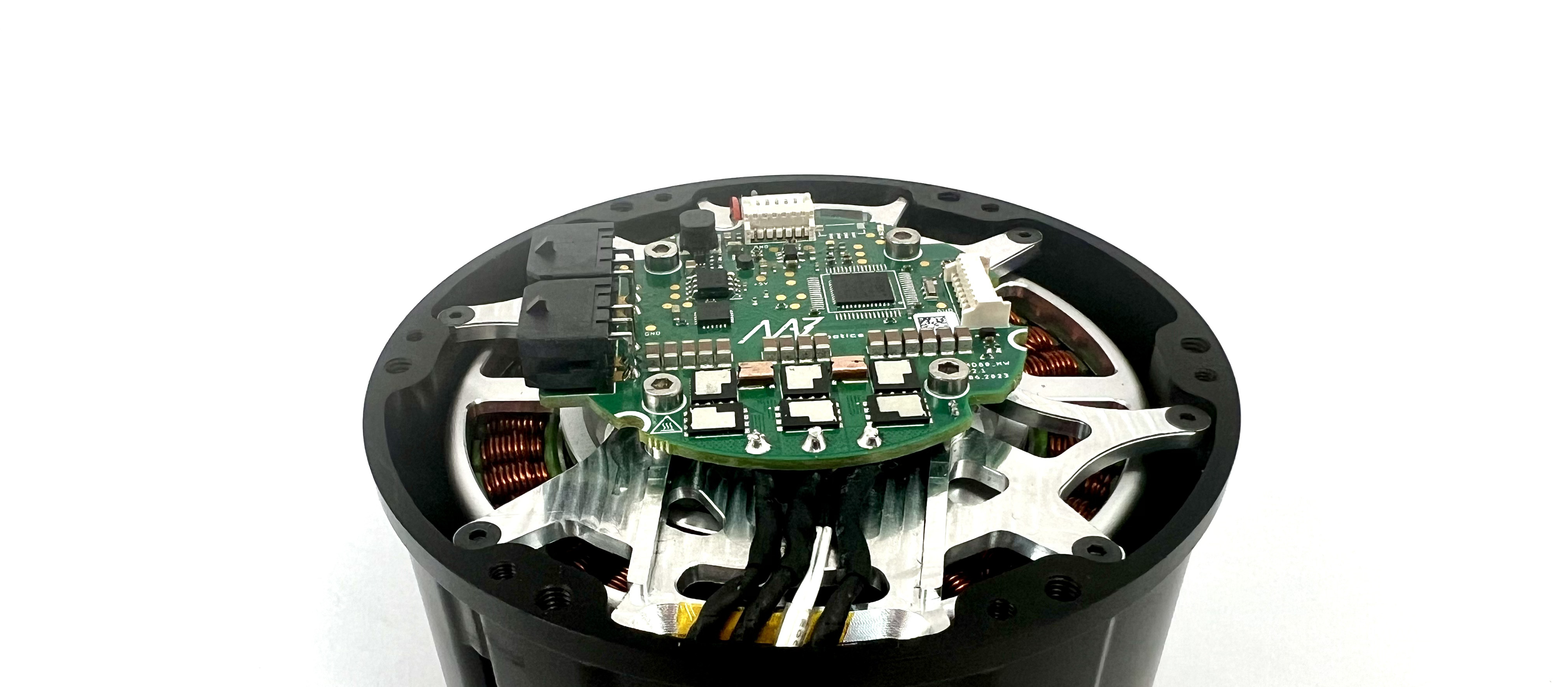
MD20#
Best for gimbal BLDC motor, and smaller motors up to 120W. 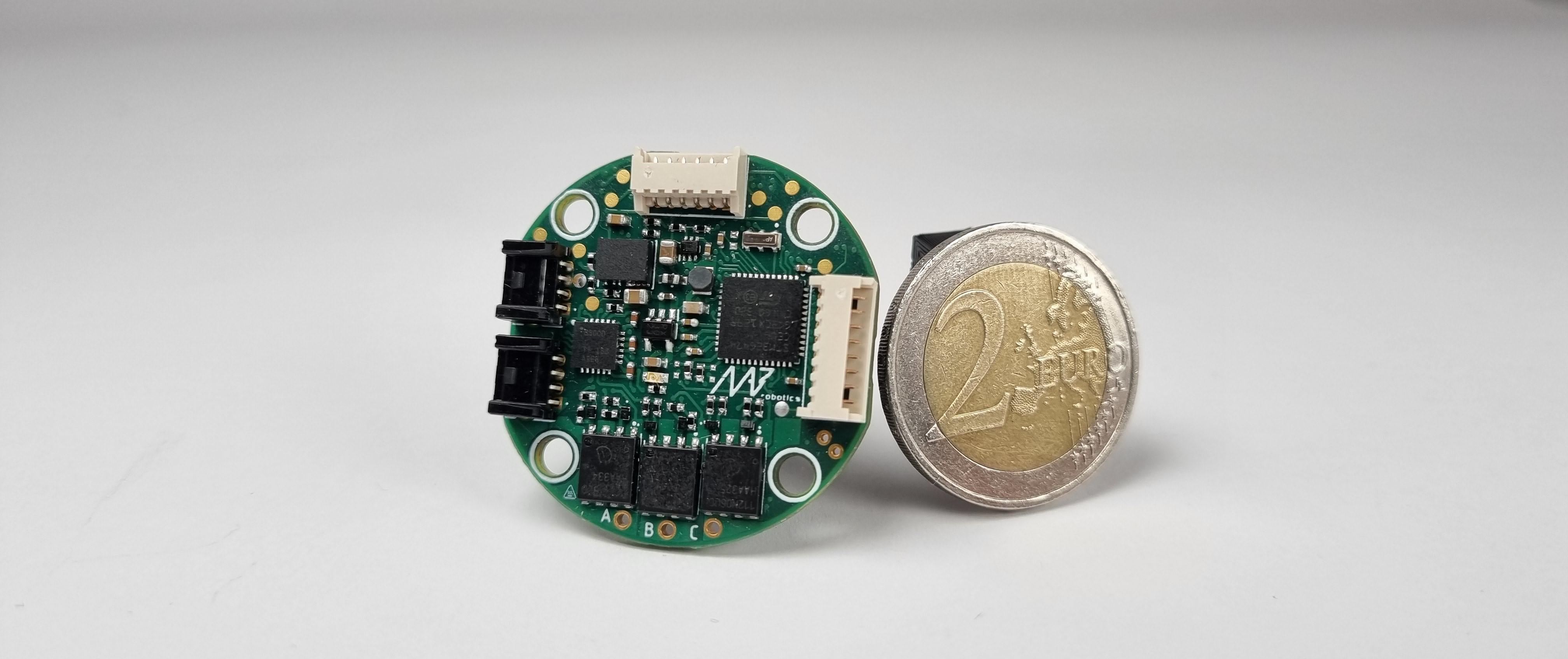
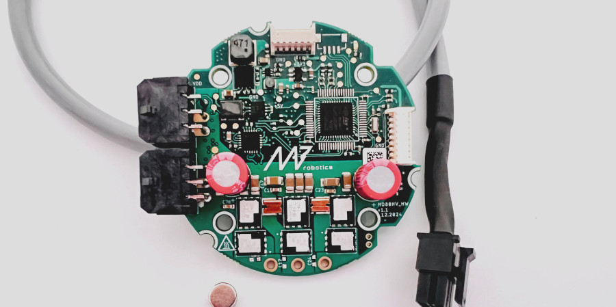
MD80 60V#
For high voltage applications.
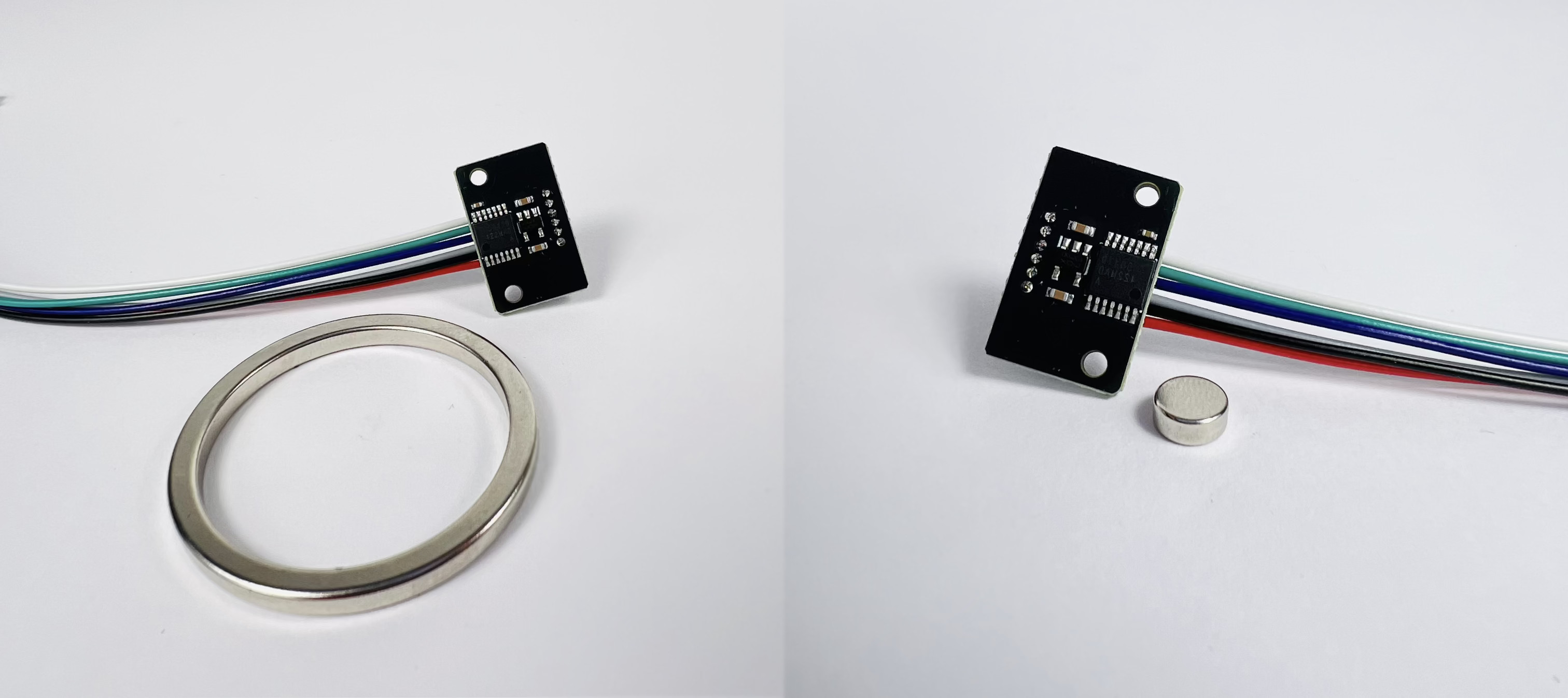
Accessories#
MD functionality can be further increased by connecting auxiliary encoders and brakes
Auxiliary Encoders#
Brake Systems#
Safety information#
Even though the MD series motor controller are small, they can push a substantial amount of current through the motor windings. This means there are many hazards related to the high torques that the actuator is able to produce as well as elevated temperatures that may occur close to the MDs or the motor. Always make sure the actuator is mounted firmly and does not pose a threat to its surroundings. Make sure the power supply current limits are set to low values (~1A) as an additional safety measure when you are unsure about the tested behavior of the system.
Principle of operation#
MD drivers are specialized FOC-based servo controllers. The controller works by using a position sensor (encoder) and measure motor currents, to control PWM signals sent to motor phases, and thus, produce precise currents in motor windings, in effect producing torque.
Current control is performed in a struct 40kHz control-loop, allowing for high-bandwidth control of dynamics system - like legged robots or drones; or to control low latency systems like collaborative manipulators.
MD drivers are equipped with sensors that allow for measuring the motor position, velocity, and torque. Whether the motor has an integrated gearbox or not, the position, velocity, and torque are in the output shaft reference frame. This means that changing the position from 0.0 to 2\(\\pi\) radians, will result in approximately one rotation of the motor for direct-drive (gearless) servos and approximately one rotation of the gearbox output shaft for geared motors.
Position#
To measure the position of the rotor the MD driver uses an internal magnetic encoder. The resolution of the encoder is 14 bits (16384 counts per rotation). The drive aggregates all the measurements to provide multi-rotation positional feedback. The reference position (0.0 rad) is set by the user and stored in the non-volatile memory. Position is measured in 40kHz loop.
Note
When using geared actuators with gear ratios above 1:1 it is not possible to determine the position after startup unambiguously, since the motor completes multiple rotations per single rotation of the output shaft. For example, for a 2:1 gearbox, there are two sections within a single output shaft rotation where the motor shaft is in the same position. Unless the motor is placed in the wrong “section” during startup the absolute encoder functionality will work. To combat this issue, an auxiliary (output) encoder can be used. See Encoders section.
Velocity#
The velocity is estimated by measuring position change in time, at a frequency of 40kHz. The measurements are then filtered using a low-pass filter with a cut-off frequency of 5 kHz since the position differentiation method introduces noise.
Torque#
Actuator torque is estimated by measuring motor phase currents. This method can be used on low-gear ratio actuators (preferably below 9:1), that are easily back-drivable, to get an estimate of the torque applied by the motor. In applications with higher gear ratios, the torque readout might be less accurate due to excessive friction in the gearbox.