Communication FDCAN#
There are two FDCAN communication connections, that have to be described. To control the PDS stack, one must connect to PDS_CTRL module, using 3-pin connector.
There are also 6-pin connectors available on PDS_PS module, that allow for connecting MD series motor controllers and other FDCAN devices. However:
Warning
PDS_CTRL FDCAN is not internally connected to PDS_PS modules. They are independent signal lines, that can be connected externally. To allow a single CANdle communicate with PDS and MD on a single string.
PDS_PS module connectors#
By default all connectors on PDS_PS module, have their CAN_H and CAN_L lines disconnected from each other, to provide only power though 6-pin connectors, allowing for up to 3 independent communication strings, to exist on the bus. There are however, bridge pads, located below 6-pin connectors to allow for connecting these buses together.
In order to connect using architecture please solder correct bridges underneath the Micro-Fit molex connector. These bridges connect CAN-L and CAN-H to another CAN-L/H of neighbor connector so the connection is transmitted without any adapters.
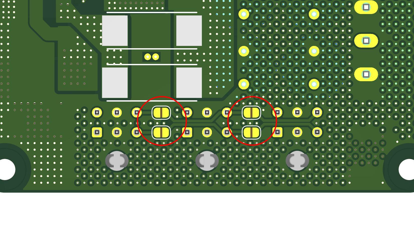
Fig. 13 FDCAN bridge placement#
Also control board has its own built-in CAN termination. If possible CAN termination should be placed on each ends of CAN circuit as shown below in recommended architecture examples.
Example 1#
In this example there are: CANdle, Control board, two Power Stage modules, six MD actuators (two per Micro-Fit molex connector) and CAN termination. In this example, termination on the CANdle is disabled.
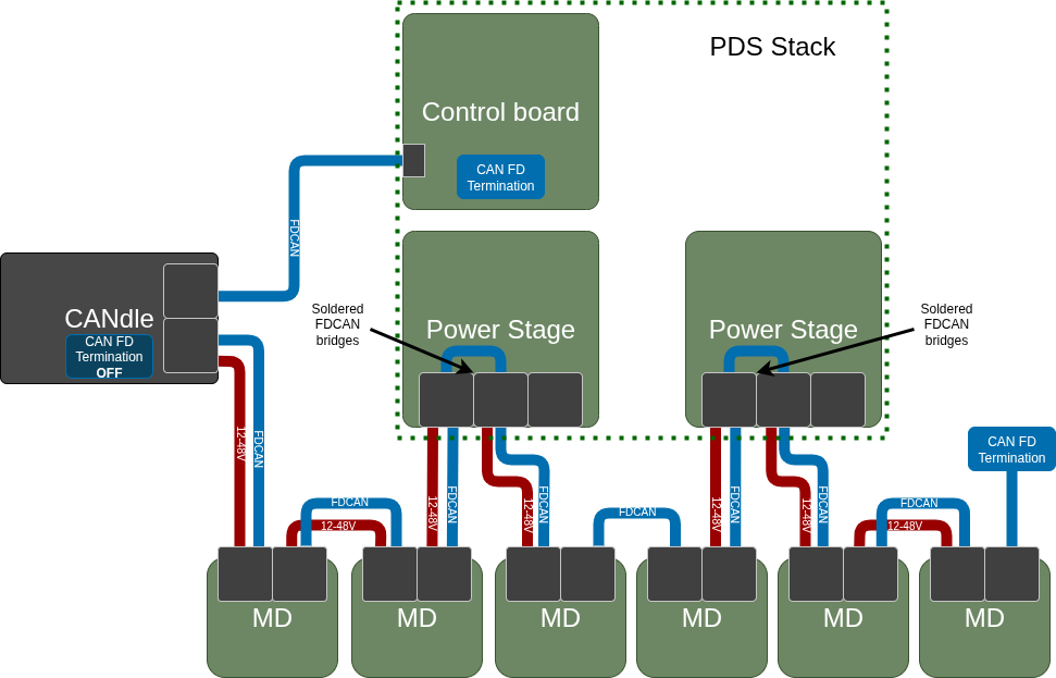
Fig. 14 FDCAN architecture with 2 Power Stage modules#
Example 2#
In this example there are: CANdle, Control board, one Power Stage module and six MD actuators (two per Micro-Fit molex connector).This is the type of example that shows how to use all ports of single Power Stage without additional CAN termination. In this example, termination on CANdle is set to ON.
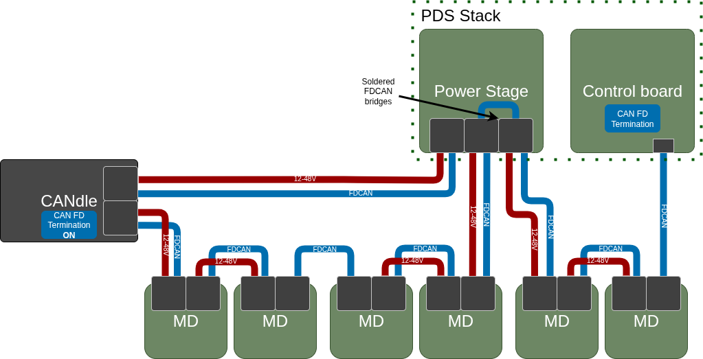
Fig. 15 FDCAN architecture with 1 Power Stage module#
Communication Protocol#
Communication with a PDS device is done with the use of the “properties” concept. Each data or setting is a property of a module that forms a PDS device stack. Each property has its own underlying data type and access rights. Each property data occupies 4 bytes on the CAN frame. When communicating with the PDS, the host controller has to form a request frame that contains:
Message type ( which indicates what the host device is about to achieve ),
Type of the module that the message is addressed to,
Socket index where the particular module is connected,
Number of properties that it is going to read or write,
A set of properties (when reading) or a property/value pairs (when writing).
Note
As in all MAB CAN-based devices, the CAN ID is used to target specific devices. PSD is not an exception. When the frame is successfully received and processed by the PDS device, its response body depends on the message type.
When the host sends a write request to a module, the module responds with a frame containing the protocol status, the number of properties received, and a status code for each property. If some properties are read-only, they will return a status of ‘NO ACCESS’, while successfully written ones will return ‘OK’. To standardize communication, Control Board is considered as a module with a socket index 0. When the host sends a request to read properties the PDS device responds in similar fashion, the protocol status code, number of properties and a set of property status / value that corresponds to the properties set in the request.
Commands#
The message frame body depends on the command code that is always placed at the beginning of the frame. For simplicity, there are only two command codes supported by the PDS device:
Read properties from the PDS module Write properties to the PDS module
Command name |
Command code [HEX] |
Description |
|---|---|---|
Read properties |
0x20 |
Read properties from the PDS module |
Write properties |
0x21 |
Write properties to the PDS module |
Properties#
Properties are the values representing some state or parameter of the module like temperature, voltage, CAN Baudrade, or module type connected to socket number 5. Obviously, not all properties are available on each module and also there are some common properties that each module must have.
NAME |
ID |
ACCESS RIGHTS |
TYPE |
DESCRIPTION |
CB |
PS |
BR |
IC |
|---|---|---|---|---|---|---|---|---|
STATUS WORD |
0x00 |
R |
U32 - btiwise |
A register were each bit represent different state of the module |
✅ |
✅ |
✅ |
✅ |
STATUS CLEAR |
0x01 |
W |
U32 - bitwise |
A register used to clear status bits in the STATUS WORD |
✅ |
✅ |
✅ |
✅ |
ENABLE |
0x02 |
RW |
Boolean |
Used to enable / disable particular module ( when write ) or simply check if it is enabled / disabled (when read ) |
✅ |
✅ |
✅ |
✅ |
TEMPERATURE |
0x03 |
R |
Float |
Module temperature |
✅ |
✅ |
✅ |
✅ |
TEMPERATURE LIMIT |
0x04 |
RW |
Float |
Temperature limit. When module temperature exceeds this value it will become disabled and unable to be enabled back until cooldown |
✅ |
✅ |
✅ |
✅ |
BUS VOLTAGE |
0x05 |
R |
U32 |
Power supply input bus voltage on control board / Power output voltage on power stage and Isolated converter |
✅ |
✅ |
❌ |
✅ |
… |
… |
… |
… |
… |
… |
… |
… |
… |
LOAD CURRENT |
0x10 |
R |
S32 |
Output current of the module |
❌ |
✅ |
❌ |
✅ |
LOAD POWER |
0x11 |
R |
S32 |
Output power of the module |
❌ |
✅ |
❌ |
✅ |
TOTAL DELIVERED ENERGY |
0x12 |
R |
U32 |
Total amount of energy ( in WH ) that was consumed by device connected to the module |
❌ |
✅ |
❌ |
✅ |
TOTAL RECUPERATED ENERGY |
0x13 |
R |
U32 |
Total amount of energy ( in WH ) that was generated by the device connected to the module |
❌ |
✅ |
❌ |
❌ |
… |
… |
… |
… |
… |
… |
… |
… |
… |
CAN ID |
0x20 |
RW |
U16 |
CAN ID |
✅ |
❌ |
❌ |
❌ |
CAN BAUDRATE |
0x21 |
RW |
ENUM* |
CAN Baudrate ( 1M / 2M / 5M / 8M ) |
✅ |
❌ |
❌ |
❌ |
SOCKET 1 MODULE |
0x22 |
R |
ENUM* |
The type of the module that is connected to socket number 1 |
✅ |
❌ |
❌ |
❌ |
SOCKET 2 MODULE |
0x23 |
R |
ENUM* |
The type of the module that is connected to socket number 2 |
✅ |
❌ |
❌ |
❌ |
SOCKET 3 MODULE |
0x24 |
R |
ENUM* |
The type of the module that is connected to socket number 3 |
✅ |
❌ |
❌ |
❌ |
SOCKET 4 MODULE |
0x25 |
R |
ENUM* |
The type of the module that is connected to socket number 4 |
✅ |
❌ |
❌ |
❌ |
SOCKET 5 MODULE |
0x26 |
R |
ENUM* |
The type of the module that is connected to socket number 5 |
✅ |
❌ |
❌ |
❌ |
SOCKET 6 MODULE |
0x27 |
R |
ENUM* |
The type of the module that is connected to socket number 6 |
✅ |
❌ |
❌ |
❌ |
SHUTDOWN_TIME |
0x28 |
RW |
U32 |
The time ( in mS ) that PDS device waits before it turns off after receiving shutdown request (either from power button or from host device ) |
✅ |
❌ |
❌ |
❌ |
BATTERY_LEVEL_1 |
0x29 |
RW |
U32 |
Levels ( in mV ) that defines ranges of battery energy available: 0 - L1 :: Almost discharged ( RED indication ), L1 - L2 :: Nominal charge ( YELLOW indication ), L2 < :: Fully charged ( GREEN indication ) |
✅ |
❌ |
❌ |
❌ |
BATTERY_LEVEL_2 |
0x2A |
RW |
U32 |
Same as above |
✅ |
❌ |
❌ |
❌ |
… |
… |
… |
… |
… |
… |
… |
… |
… |
BR SOCKET INDEX |
0x30 |
RW |
ENUM* |
Socket index of the brake resistor that we are going to bind with the power stage |
❌ |
✅ |
❌ |
❌ |
BR TRIGGER VOLTAGE |
0x31 |
RW |
U32 |
The value of the power stage output voltage above which the brake resistor will be triggered (in mV) |
❌ |
✅ |
❌ |
❌ |
… |
… |
… |
… |
… |
… |
… |
… |
… |
OCD_LEVEL |
0x40 |
RW |
U32 |
The value of current ( in mA ) above which the module will enter OCD state if this value is exceeded for a time equal or grater than the “OCD Delay” time of the same module. |
❌ |
✅ |
❌ |
✅ |
OCD_DELAY |
0x41 |
RW |
U32 |
The time ( in mS ) that the OCD level has to be exceeded for to turn the module into OCD state |
❌ |
✅ |
❌ |
✅ |
… |
… |
… |
… |
… |
… |
… |
… |
… |
HW_VERSION |
0xFD |
R |
ENUM* |
Hardware version of the module |
✅ |
✅ |
✅ |
✅ |
FW_VERSION |
0xFE |
R |
U32 - bytewise |
Firmware version of the Control board MCU |
✅ |
❌ |
❌ |
❌ |
COMMAND |
0xFF |
W |
ENUM* |
Property used to send various commands to the PDS device like ( power off, reboot, etc… ). |
✅ |
❌ |
❌ |
❌ |
Status and status clear words#
The terms ‘Status’ and ‘Status Clear’ indicate basic binary states or events within a module, such as whether it is enabled or a limit has been exceeded. The U32 bitwise type means that each bit in the value represents a different purpose rather than a singular numerical value. Like properties, status bits are module-specific—each module defines its own set, which may or may not align with those of othermodules.
NAME |
BIT POSITION |
DESCRIPTION |
CB |
PS |
BR |
IC |
|---|---|---|---|---|---|---|
Enabled |
0 |
Indicates whenever the module is enabled or not. Note that in case of Control board it indicates entire device power on status. |
✅ |
✅ |
✅ |
✅ |
Over temperature |
1 |
The temperature limit of the module has been exceeded |
✅ |
✅ |
✅ |
✅ |
Over current |
2 |
The current limit of the module has been exceeded (OCD state) |
❌ |
✅ |
❌ |
✅ |
… |
… |
… |
… |
… |
… |
… |
STO1 |
10 |
Safe Turn Off at input 1 has been triggered |
✅ |
❌ |
❌ |
❌ |
STO2 |
11 |
Safe Turn Off at input 2 has been triggered |
✅ |
❌ |
❌ |
❌ |
FDCAN Timeout |
12 |
CAN message processing timeout |
✅ |
❌ |
❌ |
❌ |
Submodule 1 error |
13 |
Some error occurs on the module connected to the socket (1 - 6). Refer to the particular module status word for more details about the issue |
✅ |
❌ |
❌ |
❌ |
Submodule 2 error |
14 |
Some error occurs on the module connected to the socket (1 - 6). Refer to the particular module status word for more details about the issue |
✅ |
❌ |
❌ |
❌ |
Submodule 3 error |
15 |
Same as above |
✅ |
❌ |
❌ |
❌ |
Submodule 4 error |
16 |
Same as above |
✅ |
❌ |
❌ |
❌ |
Submodule 5 error |
17 |
Same as above |
✅ |
❌ |
❌ |
❌ |
Submodule 6 error |
18 |
Same as above |
✅ |
❌ |
❌ |
❌ |
Charger detection |
19 |
Indicates whenever charger has been connected to the device |
✅ |
❌ |
❌ |
❌ |
Shutdown schedule |
20 |
Indicates that the PDS device shutdown has been scheduled and the PDS device is about to be turned off within the time specified in the “Shutdown time” property |
✅ |
❌ |
❌ |
❌ |
… |
… |
… |
… |
… |
… |
… |
Communication frames#
Generic frame body of the “Write property” ( 0x21 ) message:
nBytes |
1 |
1 |
1 |
1 |
1 |
4 |
… |
1 |
4 |
1 |
4 |
|---|---|---|---|---|---|---|---|---|---|---|---|
Frame field |
Write property command code [0x21] |
Module type |
Socket index |
Number of properties |
Property 1 type |
Property 1 value |
Property 2 type |
Property 2 value |
… |
Property N-1 type |
Property N-1 value |
Generic response to properties writes frame body:
nBytes |
1 |
1 |
1 |
1 |
… |
1 |
1 |
|---|---|---|---|---|---|---|---|
Frame field |
STATUS |
Number of properties |
Property 1 Status |
Property 2 Status |
… |
Property N-1 Status |
Property N Status |
Generic frame body of the “Read properties” ( 0x20 ) message:
nBytes |
1 |
1 |
1 |
1 |
1 |
1 |
… |
1 |
1 |
|---|---|---|---|---|---|---|---|---|---|
Frame field |
Read property command code [0x20] |
Module type |
Socket index |
Number of properties |
Property 1 type |
Property 2 type |
… |
Property N-1 type |
Property N type |
Generic response to properties read frame body:
nBytes |
1 |
1 |
1 |
4 |
1 |
4 |
… |
1 |
4 |
1 |
4 |
|---|---|---|---|---|---|---|---|---|---|---|---|
Frame field |
STATUS |
Number of properties |
Property 1 Status |
Property 1 value |
Property 2 Status |
Property 2 value |
… |
Property N-1 Status |
Property N-1 value |
Property N Status |
Property N value |
Response status codes#
Response to correct read or write request frames contains two different status code types. The overall message status code ( protocol status ) and per property status code ( property status ).
Overall message status codes:
Status |
Code [HEX] |
Description |
|---|---|---|
OK |
0x00 |
Request frame parsed correctly |
Invalid message length |
0x01 |
The received request frame length is incorrect. For example, when the number of properties byte indicates 4 properties but only 3 types are provided, or if the received frame length is less than the expected header. |
Invalid module type |
0x02 |
Module type code is out of range |
Invalid socket index |
0x03 |
Socket index code is out of range |
No module at socket |
0x04 |
There is no module connected to the desired socket index |
Wrong module at the socket |
0x05 |
The desired module type does not match the one actually connected to the desired socket |
Properties status codes:
Status |
Code [HEX] |
Description |
|---|---|---|
OK |
0x00 |
Property read/write operation success |
No property |
0x01 |
The addressed module does not support the requested property |
Invalid access rights |
0x02 |
Requested read operation from write-only property or write operation to read-only property |
Invalid data argument |
0x03 |
Given data value during the write operation is invalid. For example, when the user is trying to exceed some limit or pass a value that is out of valid enumeration range |