Status#
When an abnormal situation takes place the controller sets an error bit indicating a particular
error or warning. The table below lists all available error and warning codes and their
descriptions. The easiest way to check all statuses is to use candletool md info. Another way
could be to use the CANdle lib register access and read the statuses, or decode the general “Quick
Status” using the CANdle lib getQuickStatus() function.
Errors and warnings can be cleared by register access, or using candletool md clear command.
Please note that all warnings and only non-critical errors can be cleared.
Quick Status#
Quick status provides a general info about errors in each category of statuses. No warnings are indicated here. Last bit indicatest whether the current target (position or velocity) has been reached.
| Error bit | Error description | |
| 0 | Main encoder error | |
| 1 | Output encoder error | |
| 2 | Calibration encoder error | |
| 3 | MOSFET bridge error | |
| 4 | Hardware errors | |
| 5 | Communication errors | |
| 6 | Motion errors | |
| 8-14 | RESERVED | |
| 15 | Target position or velocity reached* |
*This bit is only set in the according to following conditions:
in Position PID and Profile Position modes, when position was reached within position window,
in Velocity PID and Profile Velocity modes, when velocity was reached within velocity window.
Main / Output Encoder Errors#
| Error name | Error bit | Error description | Action to clear it |
| ERROR_COMMUNICATION | 0 | MDxx could not communicate with the encoder | Check connections |
| ERROR_WRONG_DIRECTION | 1 | Indicates the calibrated output encoder direction is different from the main encoder direction | Recalibrate |
| ERROR_EMPTY_LUT | 2 | Indicates the encoder eccentricity table is empty | Recalibrate |
| ERROR_FAULTY_LUT | 3 | Indicates the encoder eccentricity table is faulty (contains too large corrections) | Check the setup and recalibrate |
| ERROR_CALIBRATION_FAILED | 4 | Calibration failed due to wrong motor <> encoder setup | Check setup, recalibrate in case of problems contact MABRobotics |
| ERROR_POSITION_INVALID | 5 | Position reading is invalid | Check encoder physical setup, in case of problems contact MABRobotics |
| ERROR_INIT | 6 | Encoder initialization failed | Check encoder setup and connection, in case of problems contact MABRobotics |
| WARNING_LOW_ACCURACY | 30 | Encoder position readout accuracy may be lower than specified | Check encoder physical setup and reboot the MDxx |
Calibration Errors#
| Error name | Error bit | Error description | Action to clear it |
| ERROR_OFFSET_CAL | 0 | Problem with the offset determination during calibration | Try recalibrating. |
| ERROR_RESISTANCE_IDENT | 1 | Problem with resistance identification | Try recalibrating or running the `candletool md calibration` command |
| ERROR_INDUCTANCE_IDENT | 2 | Problem with inductance identification | Try recalibrating or running the `candletool md calibration` command |
| ERROR_POLE_PAIR_CAL | 3 | Problem with pole pair detection routine | Try recalibrating |
| ERROR_SETUP | 4 | Problem with motor config file download, or the setup parameters themselves | Check the config file again and try to upload one more time |
Bridge errors#
| Error name | Error bit | Error description | Action to clear it |
| ERROR_BRIDGE_COM | 0 | Communication problem with the bridge | Contact MABRobotics |
| ERROR_BRIDGE_OC | 1 | The bridge detected overcurrent | Lower the current limit, clear the error or restart the drives |
| ERROR_BRIDGE_GENERAL_FAULT | 2 | Usually indicates a hardware issue | Contact MABRobotics |
Hardware errors#
| Error name | Error bit | Error description | Action to clear it |
| ERROR_OVER_CURRENT | 0 | Overcurrent detected | Increase the current limit, clear the error or restart the drive |
| ERROR_OVER_VOLTAGE | 1 | Overvoltage detected | Lower the system voltage, avoid rapid braking in the system, use a modern PSU, or a LiPo battery |
| ERROR_UNDER_VOLTAGE | 2 | Undervoltage detected | Ensure your power supply has enough current capability for your system |
| ERROR_MOTOR_TEMP | 3 | Motor temperature exceeded the limit set in the config file | Wait for the motor to cool down |
| ERROR_MOSFET_TEMP | 4 | MDxx power side exceeded the limit of 100*C | wait for the MD to cool down |
| ERROR_ADC_CURRENT_OFFSETS | 5 | Error during adc current offsets calibration | Usually indicates a hardware error - contact MABRobotics |
Communication errors#
| Error name | Error bit | Error description | Action to clear it |
| WARNING_CAN_WD | 30 | Indicates the communication with the host was ended by the watchdog | Send any valid CAN frame to MD. |
Motion status#
| Error name | Error bit | Error description | Action to clear it |
| ERROR_POSITION_OUTSIDE_LIMITS | 0 | Current shaft position is outside the |
Re-home the actuator, set a temporary zero to move it back into the limits, or increase the limit range, clear using candletool |
| ERROR_VELOCITY_OUTSIDE_LIMITS | 1 | Velocity exceeded the max velocity param | Ensure the velocity limit is set to a proper value, clear using candletool |
| WARNING_ACCELERATION_CLIPPED | 24 | Acceleration command was clipped to max acceleration at least once | Check acceleration limits, clear using candletool |
| WARNING_TORQUE_CLIPPED | 25 | Torque command was clipped to max torque at least once | Check torque limits, clear using candletool |
| WARNING_VELOCITY_CLIPPED | 26 | Velocity command was clipped to max velocity at least once | Check velocity limits, clear using candletool |
| WARNING_POSITION_CLIPPED | 27 | Position command was clipped to either max or min position at least once | Check position limits, clear using candletool |
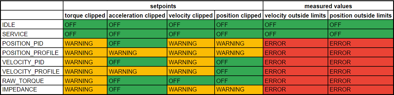
The following table shows when warnings and errors are issued based on the mode the controller is currently in:
Utilities#
GPIO#
All of the MD controllers have two multi-purpose GPIO pins. Currently they have two functionalities:
Auto Brake - in this mode MD will automatically engage MABs provided braking systems via GPIO A pin, see brake systems and registers section for more details.
GPIO input - in this mode MD will output GPIO pin states to state register (userGpioState 0x161)
Important
The GPIO are connected directly to board’s MCU. DO NOT drive this pins higher than +5V or lower than 0V as this WILL damage the board.
Also the GPIO pins are floating so if you want to use those pins as an external function switches, do so with proper pull-up/down resistor or push-pull circuitry.