Control board#
General specification#
The PDS_CTRL module serves as the central controller in the system. Its main functions include:
managing and acquiring data from up to six connected modules,
facilitating communication over CAN FD with support for integration into the CANdle ecosystem,
handling the RGB switch for powering the system on and off, with status reporting via the RGB diodes,
the monitoring input voltage,
tracking temperature across the system,
managing Safe Turn Off (STO) inputs ensures safe operation in critical situations.
Parameter |
Value |
|---|---|
Input voltage |
12–54 V |
Max number of slave modules |
6 |
FDCAN Baudrate (adjustable) |
1 / 2 / 5 / 8 Mbps |
Current consumption on standby (without slave modules) |
37.5 mA |
Quiescent current in shutdown |
11.63 µA |
Mass |
36 g |
Ambient Temperature (Operating) |
0–40 ℃ |
Ambient Temperature (Non-operating) |
0–60 ℃ |
Maximum Humidity (Operating) |
up to 95% |
Maximum Humidity (Non-operating) |
up to 95% |
Altitude (Operating) |
–400 m to 2000 m |
Ports and communication#
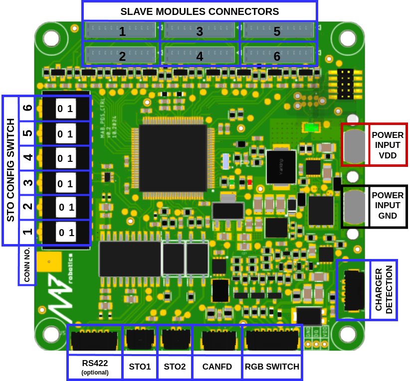
Fig. 4 Control board with highlighted ports#
Connector Name |
Included Cable Specification |
Wiring Details |
|---|---|---|
SLAVE MODULES CONNECTORS |
10-pin Molex PicoBlade |
Connect to each submodule |
STO1/2 |
2-pin Molex Microlock 1m |
Connect normally closed switch to safe supply (12–30V) |
FDCAN |
3-pin Molex Microlock 1m |
Non-isolated FDCAN port for communication via CANdle or custom FDCAN |
CHARGER DETECTION |
Optional |
Port to detect charging. Connect to charging add-on module |
RS422 |
Optional |
RS422 port with isolated power included on request |
RGB SWITCH |
6-pin Molex Microlock |
RGB switch port. Switch enables PDS and indicates states |
The CAN FD interface in the PDS is designed to provide essential telemetry data, including information on currents, voltages, and temperature, as well as to facilitate the configuration and control of the system. Its transceiver is non-isolated with split termination on board and operates up to 8-Mbps. In order to connect FDCAN with PDS system user needs to connect FDCAN directly to Control Board. Please take a look at examples of recommended architecture.
Safety Turn Off#
The PDS includes a safety mechanism for controlled power shut-off, similar to those found in standard motor controllers. It features two input channels, each capable of independently disconnecting power from the connected loads, ensuring safe operation. The inputs are protected against reverse polarity.
Each slave module can be integrated into the safety mechanism by setting the STO configuration switch accordingly.
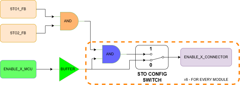
Fig. 5 STO1/2 logic circuit#
Truth table for STO1/2 logic:
STO1_FB |
STO2_FB |
ENABLE_X_MCU |
STO_CONFIG_SWITCH |
ENABLE_X_CONNECTOR MODULE ENABLE INPUT STATE |
|---|---|---|---|---|
X |
X |
0 |
X |
0 |
X |
X |
1 |
0 |
1 |
0 |
0 |
1 |
1 |
0 |
1 |
0 |
1 |
1 |
0 |
0 |
1 |
1 |
1 |
0 |
1 |
1 |
1 |
1 |
1 |
Summarizing:
If STO_CONFIG_SWITCH is in position 0, the ENABLE state set by MCU is passed directly to the output, regardless of the status of STO1_FB and STO2_FB
If STO_CONFIG_SWITCH is in position 1, the ENABLE state set by MCU is passed to the output only when the STOx_FB signals state is 1
RGB SWITCH#
This port is dedicated to connecting the RGB switch which enables the PDS and reports the system state with the RGB diodes.
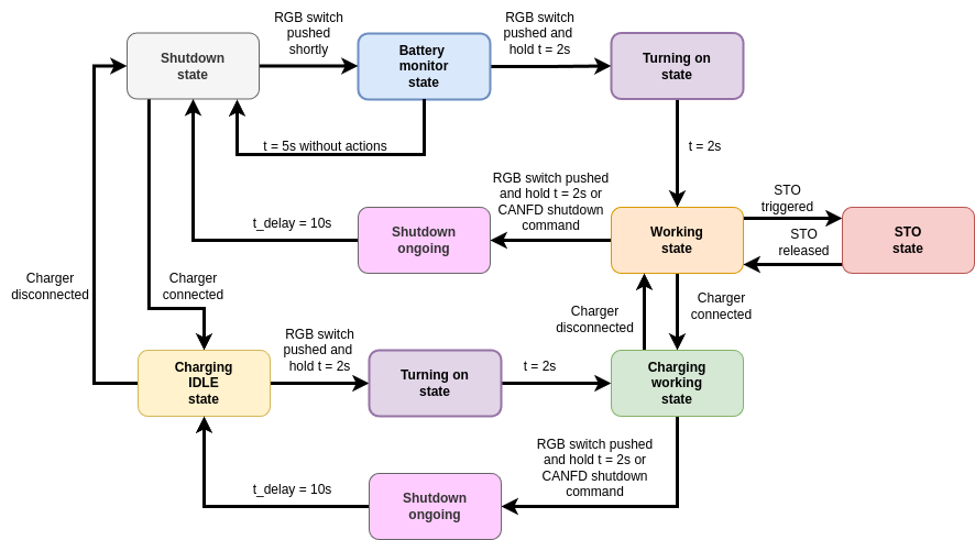
Fig. 6 States and transitions on RGB switch#
State |
Description |
|---|---|
Shutdown |
PDS is turned off with a quiescent current of approximately 20 µA. |
Battery monitor |
PDS shows the battery charge level with respect to the user-predefined voltage levels. In this state, all slave modules are turned off. |
Charging |
PDS slave modules are turned off. The CTRL module is enabled. The battery is charging. RGB button blinks slowly with color dependent on the battery voltage. |
Operating |
Normal operation. RGB switch indicates battery level same way as in battery monitor state. If the charger is connected, the RGB switch additionally blinks slowly with BLUE/BAT_LEVEL color alternately. |
STO |
Device generally works as in operating state but RGB LED indicates an STO event by blinking RED / YELLOW. |
Shutdown ongoing |
All submodules except isolated converters are disabled. RGB switch turns solid WHITE. |
Battery Level can be set in software using:
setBatteryVoltageLevels(u32 batteryLvl1, u32 batteryLvl2) //CANdle-SDK

set_battery_level <level1> <level2> //candletool
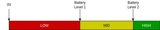
Fig. 7 Battery levels and according color of RGB switch#
More information about commands in CANdle-SDK PDS commands and candletool for PDS